
Dynamic threshold P-channel MOSFET for ultra-low voltage ultra-low power applications

a mosfet and dynamic threshold technology, applied in the field of mosfet devices with adaptive body biases, can solve the problems of high power consumption, weak battery life demands, and slow circuits, and achieve the effects of less power consumption, minimizing or eliminating the effect of glitches at the output node, and eliminating unnecessary pmos transistors' body switching activity

Inactive Publication Date: 2007-11-22
UNIVERSITY OF LOUISIANA AT LAFAYETTE
View PDF1 Cites 2 Cited by
  • Summary
  • Abstract
  • Description
  • Claims
  • Application Information

AI Technical Summary

Benefits of technology

[0019] One advantage of the present invention is that it eliminates unnecessary PMOS transistors' bodies switching activity when their corresponding inputs to the PMOS gates switch.
[0020] Another advantage of the present invention is that it minimizes or eliminates glitches at the output node.
[0021] Another advantage of the present invention is that uses less power than the prior art schemes.
[0022] One more advantage of the present invention is that it reduces the load on the input signals at the PMOS transistors' gates leading to faster operation and lower circuit delay.
[0023] One further advantage of the present invention is that it reduces the unnecessary high current which was supplied in the prior art schemes even when the transistor circuit's output has made the switching.

Problems solved by technology

Battery-operated low-to-moderate performance requirements applications (such as pacemakers, hearing aids, wrist watches, and calculators) have very strong demands on battery lifetime and consequently on power consumption.
This subthreshold leakage current is orders of magnitude lower than the strong inversion current which leads to the desired ultra-low power consumption; however, it also leads to a much slower circuit.
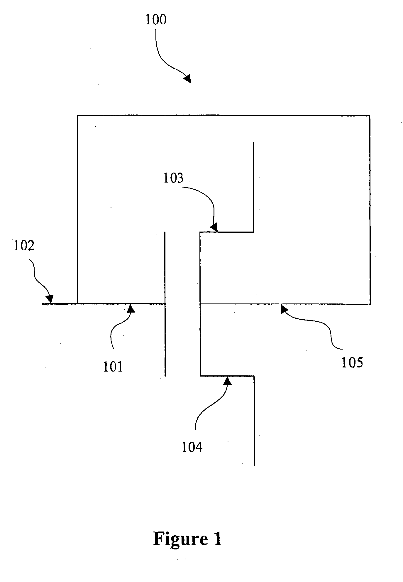
The effective gate capacitance at the gate 101 of a DTMOS is larger than the gate capacitance of a regular MOSFET, but the higher driving current available when input 102 is high diminishes this problem and causes the DTMOS circuit to have less delay than the regular MOS circuits.

Method used


Image

  • Dynamic threshold P-channel MOSFET for ultra-low voltage ultra-low power applications
  • Dynamic threshold P-channel MOSFET for ultra-low voltage ultra-low power applications
  • Dynamic threshold P-channel MOSFET for ultra-low voltage ultra-low power applications

Examples


Embodiment Construction

[0028] In the following detailed description of the embodiments reference is made to the accompanying drawings. The drawings are intended to show, by way of illustration, specific embodiments in which the invention may be practiced; like reference numerals in text refer to like elements in drawings. It is to be understood that other embodiments of the invention may be utilized and structural changes may be made without departing from the scope of the present invention.

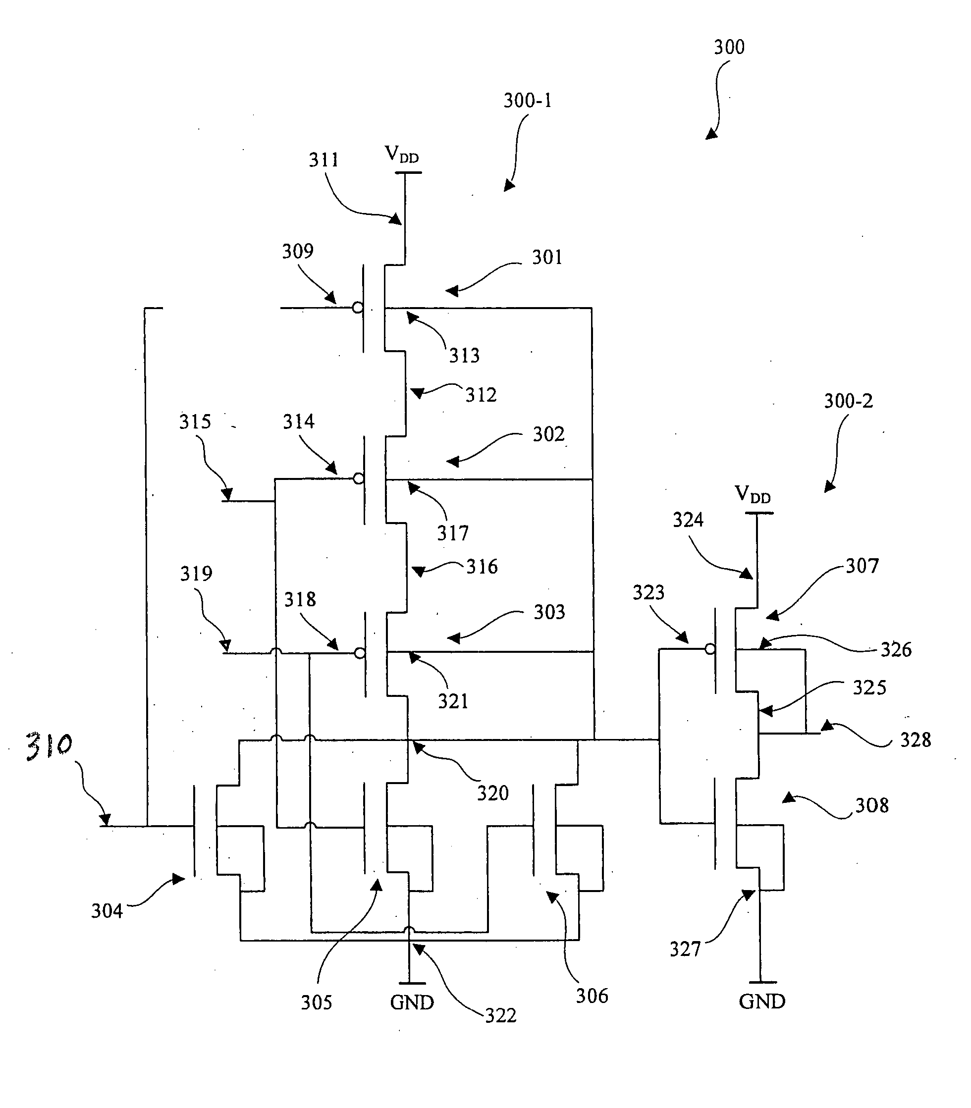
[0029]FIG. 3 illustrates the use of the first preferred embodiment of the present invention in constructing a 3-input OR transistor circuit 300. The 3-input OR transistor circuit 300 comprises a 3-input NOR transistor circuit 300-1 and a CMOS inverter 300-2. The output of the 3-input NOR transistor circuit 300-1 is connected to the input of the CMOS inverter 300-2.

[0030] The 3-input NOR transistor circuit comprises three PMOS transistors 301, 302, and 303 connected in series between the internal signal nodes 311 and ...


PUM


Abstract

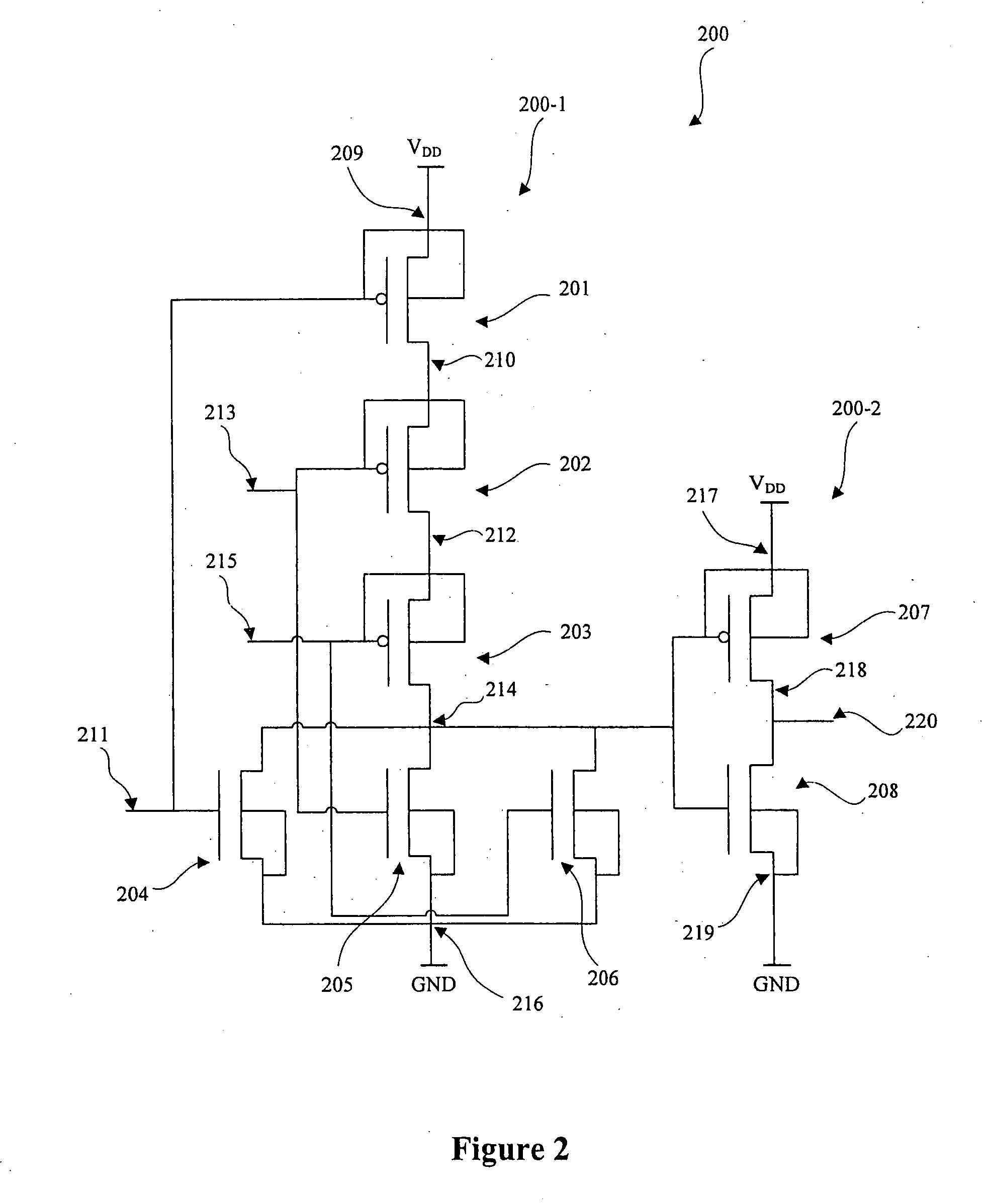
A dynamic threshold voltage p-channel MOSFET (PMOS) for ultra-low power ultra-low voltage applications is disclosed. These applications are of low-to-moderate performance requirements; hence ultra-low voltage subthreshold operation, where the supply voltage is less than the transistors threshold voltage, is suitable. By tying the PMOS body to the output node of the transistor circuit in which this PMOS is part of will provide the necessary body bias for this PMOS threshold voltage to change dynamically with the circuit's output status. The dynamic change of the PMOS transistor threshold voltage will consequently dynamically increase or decrease the subthreshold leakage current which is the switching current in subthreshold circuits.

Description

BACKGROUND OF THE INVENTION [0001] 1. Field of the Invention [0002] This invention relates generally to MOSFET devices and integrated circuits and particularly to MOSFET devices with adaptive body biases for operating- and off-conditions. More particularly, this invention relates to a method of generating the MOSFET device body bias which leads to low threshold operating voltage and high threshold voltages during off-conditions. The devices in the present invention exhibit low currents during off-conditions and high currents during on-conditions which makes them suitable for ultra-low operating voltage ultra-low power operations. [0003] 2. Description of the Background Art [0004] The continuing growth of battery-operated devices market has increased the demand for low-energy VLSI design. Battery-operated low-to-moderate performance requirements applications (such as pacemakers, hearing aids, wrist watches, and calculators) have very strong demands on battery lifetime and consequentl...

Claims


Application Information

Patent Timeline
Patent Type & Authority Applications(United States)
IPC IPC(8): H01L29/76
CPCH04R3/00
Inventor ELGHARBAWY, WALID M.BAYOUMI, MAGDY A.
Owner UNIVERSITY OF LOUISIANA AT LAFAYETTE
Learn More