Flight control systems

a control system and flight control technology, applied in the field of flight control systems, can solve the problems of limited work available at the control surface, inability to provide redundancy, and poor failure tolerance of mechanical systems, so as to achieve sufficient back-up controls and improve overall flight control operation.

Active Publication Date: 2007-11-22
TEXTRON INNOVATIONS
View PDF41 Cites 23 Cited by
  • Summary
  • Abstract
  • Description
  • Claims
  • Application Information

AI Technical Summary

Benefits of technology

[0009] The present invention is defined by the claims below. Embodiments of the present invention solve at least the above problems by providing a system and method for controlling aircraft flight control surfaces both manually and through a computing device. The system improves overall flight control operation by reducing the manual flight control surface requirements, supplementing those controls with powered controls, and providing sufficient back-up controls in the event of failures.

Problems solved by technology

While manually operated control systems provide a direct and reliable link between the operator's input and the movement of the aircraft control surfaces, these mechanical systems tend to have a poor failure tolerance, and as such, require redundant and independent load paths for continued safe flight and landing, in the event of a failure.
As a result, additional hardware and mechanisms are required to provide this redundancy.
With a manual system, the work available at the control surface is limited by the force and travel that an operator can apply to the cockpit controls.
As the speed and size of aircraft increase, manual control of the aircraft becomes inadequate to effectively maneuver the aircraft.
However, these systems add complexity and additional failure modes.
For example, fully powered systems are dependent on their power sources, which themselves must be highly redundant.
Failure of a fully powered system, without having a manual reversion or back-up, would result in complete failure, and lack of control, of any aircraft control surface.
Furthermore, fully powered systems do not provide natural force feedback to the operator.
However, fully powered and completely computerized controls, such as fly-by-wire, are not warranted.

Method used


Image

  • Flight control systems
  • Flight control systems
  • Flight control systems

Examples


first embodiment

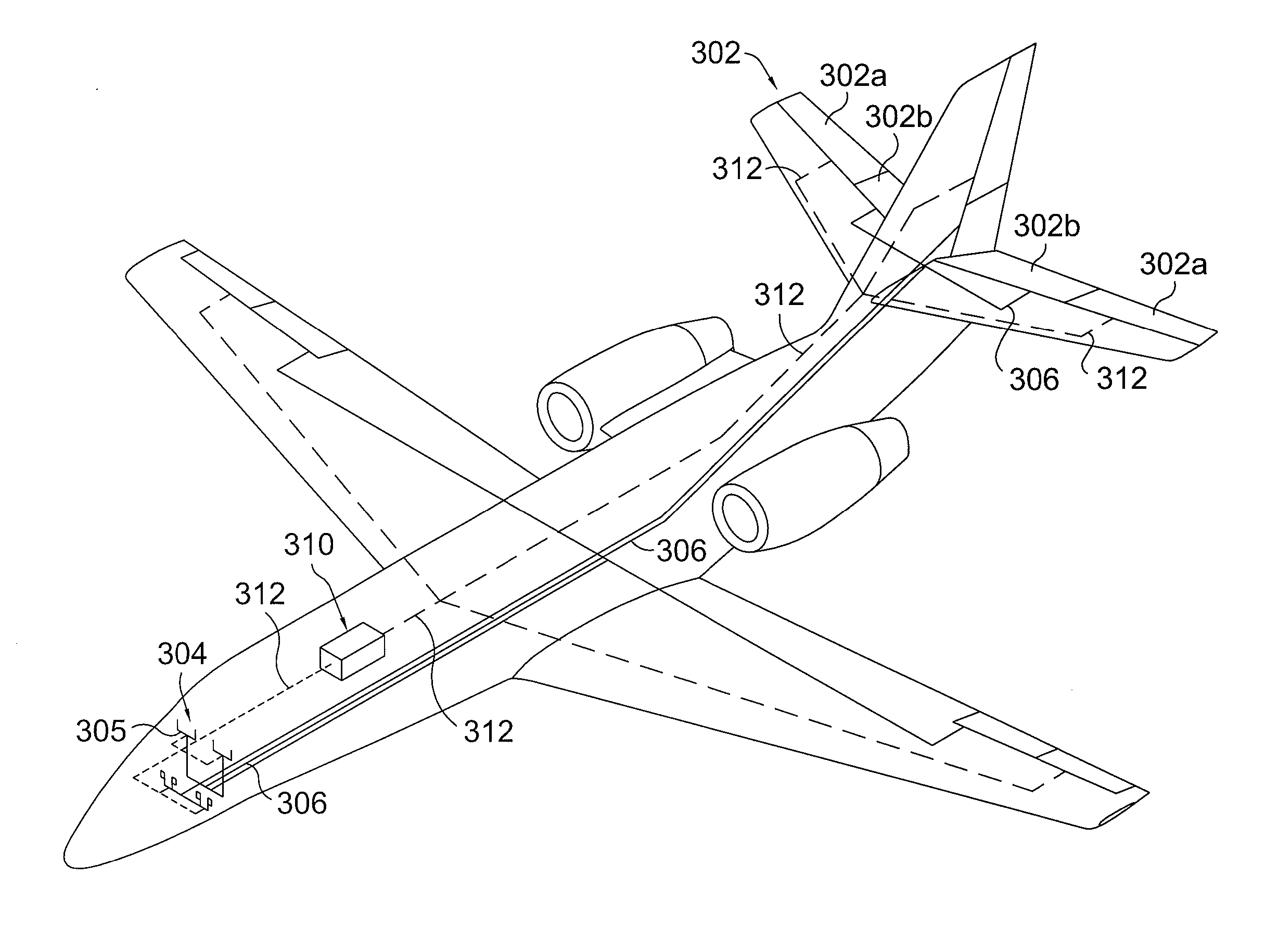
[0044] For aircraft operating with significantly more gross weight and at even higher airspeeds, e.g., commercial jetliners, the reversible mechanical manual portion of the system described in the above may prove insufficient. Referring back to the first embodiment disclosed in FIG. 4, the mechanical arrangement comprising control means / stick 304 and link 306 may be unable to provide the power necessary to properly actuate control surface 302b, and variations in the control surface hinge moments may be unable to provide the appropriate feedback and feel to the pilot.

[0045] Under these circumstances, a second embodiment like that shown in FIG. 7 may be preferred. As can be seen from the figure, this embodiment 700, like the first, comprises at least one control surface 702 having a plurality of individual segments 702a and 702b. Like with the first embodiment, surfaces 702a are operated using electronically controlled servo-actuators 708. And also like the first embodiment, a mechani...

second embodiment

[0047] When the pilot moves the cockpit controls 704 from a first position to a second position, device 714 will receive the resulting mechanical displacement through linkage 706 and provides the force necessary to rotate control surface 702b to a corresponding and directly related angular displacement. Cockpit controls 704 are shown as being hand operated in FIG. 7, but could alternatively be a foot-operated arrangement. In the preferred embodiment, power control device 714 is a mechanically driven power control unit (PCU). One skilled in the art will recognize that mechanically driven PCUs are commercially available powered devices which are typically mounted on the trailing edge or other longitudinal stabilizing surface of the aircraft and can be used to obtain pitch-control moments. The mechanically-driven variety used herein receive mechanical input from an input rod and then irreversibly produce an output having the force necessary to create a corresponding angular displacemen...


PUM


Abstract

A system and method for a controlling an aircraft with flight control surfaces that are controlled both manually and by a computing device is disclosed. The present invention improves overall flight control operation by reducing the mechanical flight control surface components while providing sufficient back-up control capability in the event of either a mechanical or power-related failure. Through the present invention, natural feedback is provided to the operator from the mechanical flight control surface which operates independent of computer-aided flight control surfaces.

Description

CROSS-REFERENCE TO RELATED APPLICATIONS [0001] This application is a continuation in part of and claims the benefit of U.S. patent application Ser. No. 11 / 383,791 filed May 17, 2006, the disclosure of which is incorporated herein by reference.BACKGROUND OF THE INVENTION [0002] 1. Field of the Invention [0003] The invention relates generally to methods of controlling an aircraft in flight. More specifically, the invention relates to the field of manipulating control surfaces on an aircraft, e.g., ailerons, flaps to aerodynamically control flight characteristics. [0004] 2. Description of the Related Art [0005] Aircraft are typically controlled by moveable aerodynamic surfaces on the wing and tail for controlling the altitude and attitude of the aircraft in flight, including roll, pitch, and yaw. Small aircraft can use simple mechanical linkages to transmit the operator's control inputs to these surfaces. Larger and faster aircraft need power assisted or fully-powered control systems. ...

Claims


Application Information

Patent Timeline
Patent Type & Authority Applications(United States)
IPC IPC(8): B64C13/50B64C13/38
CPCB64C9/04B64C13/503B64C13/38B64C9/10B64C13/507
Inventor CIHOLAS, PHILIPPE A.PALMER, MARK W.
Owner TEXTRON INNOVATIONS
Why Eureka
Try Eureka