
Passenger restraining protective system

a protective system and passenger technology, applied in the direction of belt retractors, belt control systems, vehicle components, etc., can solve the problems of difficult installation of the motor-based first pretensioner, large deceleration of the vehicle, and inability to ensure the operation of the second pretensioner, etc., to achieve easy operation control

Inactive Publication Date: 2004-03-09
JOYSON SAFETY SYST JAPAN KK
View PDF20 Cites 45 Cited by
  • Summary
  • Abstract
  • Description
  • Claims
  • Application Information

AI Technical Summary

Benefits of technology

is to provide a passenger restraining protective system which not only better facilitates installation of the first and second pretensioners, but also permits easier operational control thereof. another object of the invention is to provide a passenger restraining protective system which eliminates the necessity to provide a locking mechanism locking drawout of the webbing upon operation of the first pretensioner on the seat belt retracting apparatus.
In the passenger restraining protective system of the invention, when a collision is determined, the second pretensioner is preferentially operated by the controller, irrespective of the operation of the first pretensioner, to set a second set tension higher than the first set tension that would result from the first pretensioner. As a result, even in case of a collision which cannot be detected by a conventional sensor for predicting a collision as described above, the passenger is restrained and protected by a strong restraining force. Particularly, when the first pretensioner is provided in the seat belt retracting apparatus, the necessity to control the operation of the second pretensioner during operation of the first pretensioner is eliminated. Further, it is not required any longer to lock the seat belt taken up on the retractor from withdrawal since such withdrawal is prevented.
In the present invention, the first pretensioner requiring a relatively large space for installation can be provided in the seat belt apparatus and the second pretensioner requiring a relatively small installation space can be provided on the buckle side. This makes it easier to install the pretensioner on the buckle side where only a small space is available.
Further, operation of the first pretensioner can be continued even after operation of the second pretensioner, until and unless the possibility of a collision is resolved. When a is driven after a slight collision, the slack of the webbing can therefore be removed without fail, thus permitting restraint of the passenger.

Problems solved by technology

Such an emergency is a collision where the vehicle undergoes a large deceleration.
As a result, for example, when a car suddenly rushes out from the side in front of a car mounting a frontward collision predicting sensor, the collision predicting sensor cannot detect the rushing car in time, and it may be difficult for the sensor to output an operating signal of the second pretensioner before a collision or upon a collision, thus making it impossible to certainly cause the second pretensioner to operate when the collision cannot be avoided.
When the first pretensioner with the motor is provided on the buckle side, a problem occurs.
Installation of the motor-based first pretensioner is difficult because the space available on the buckle side is very limited, while the installation of the motor may require a relatively large space.
This leads to more complicated control of various operations of the first and second pretensioners, to the necessity of providing a locking mechanism which locks drawout of the webbing upon operation of the first pretensioner, and to a troublesome operational control of the locking mechanism.
In the case of a slight collision, when the car is driven again after operation of the second pretensioner, it is difficult to control operation of the retractor and the slack of the webbing cannot be eliminated, making it difficult to restrain and hold the passenger.

Method used


Image

  • Passenger restraining protective system
  • Passenger restraining protective system
  • Passenger restraining protective system

Examples


Embodiment Construction

Embodiments of the present invention will now be described with reference to the drawings.

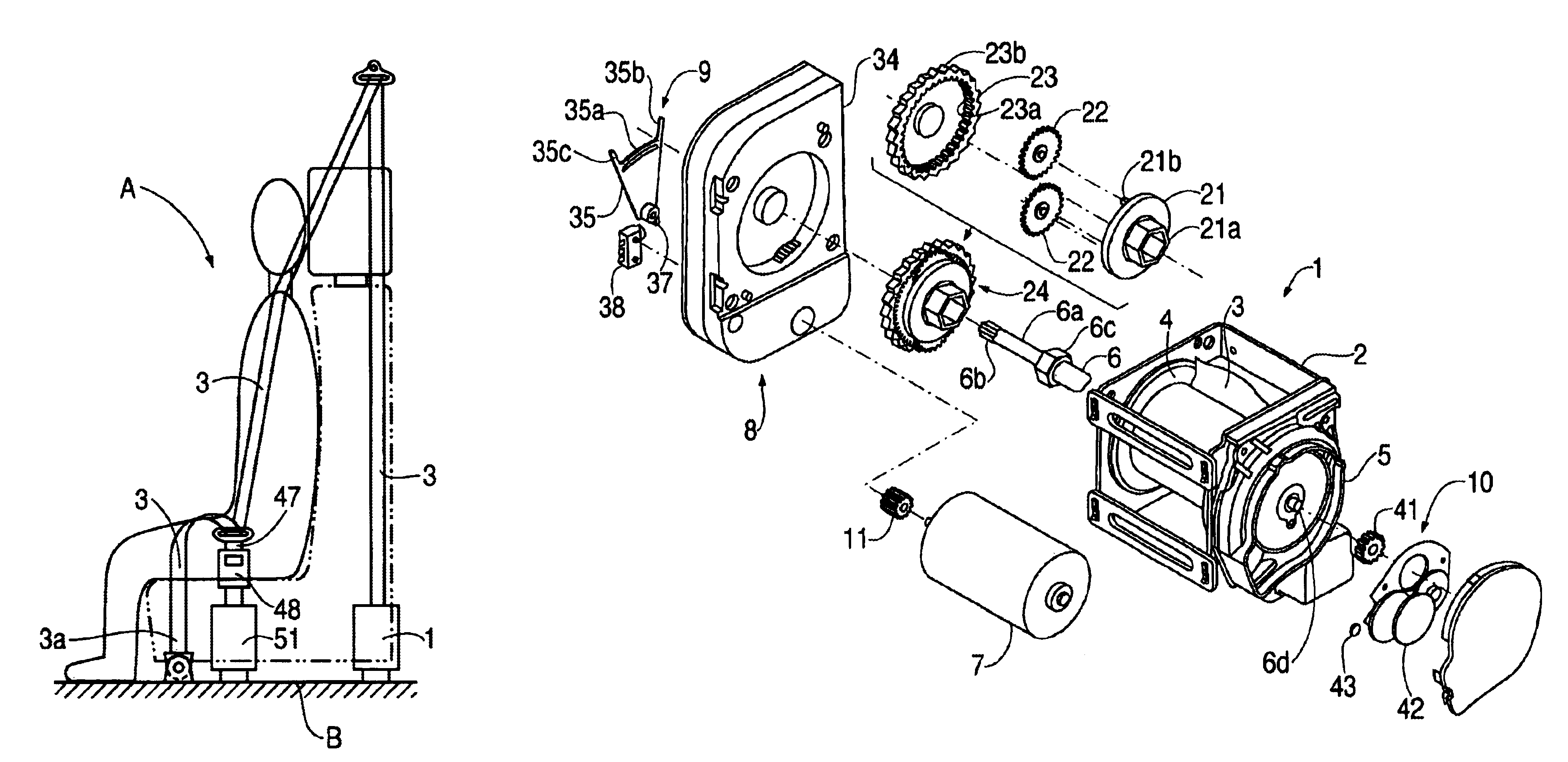
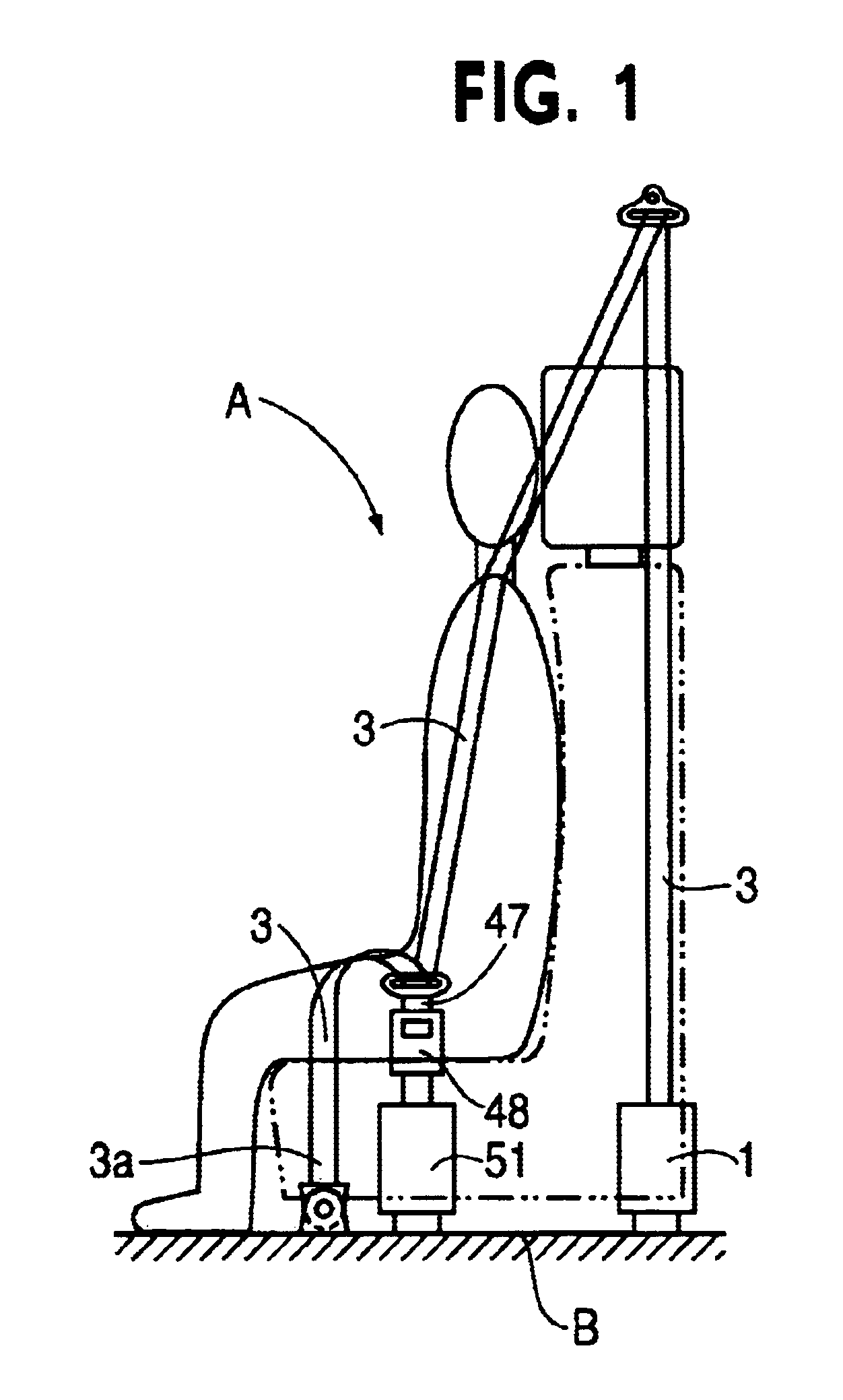
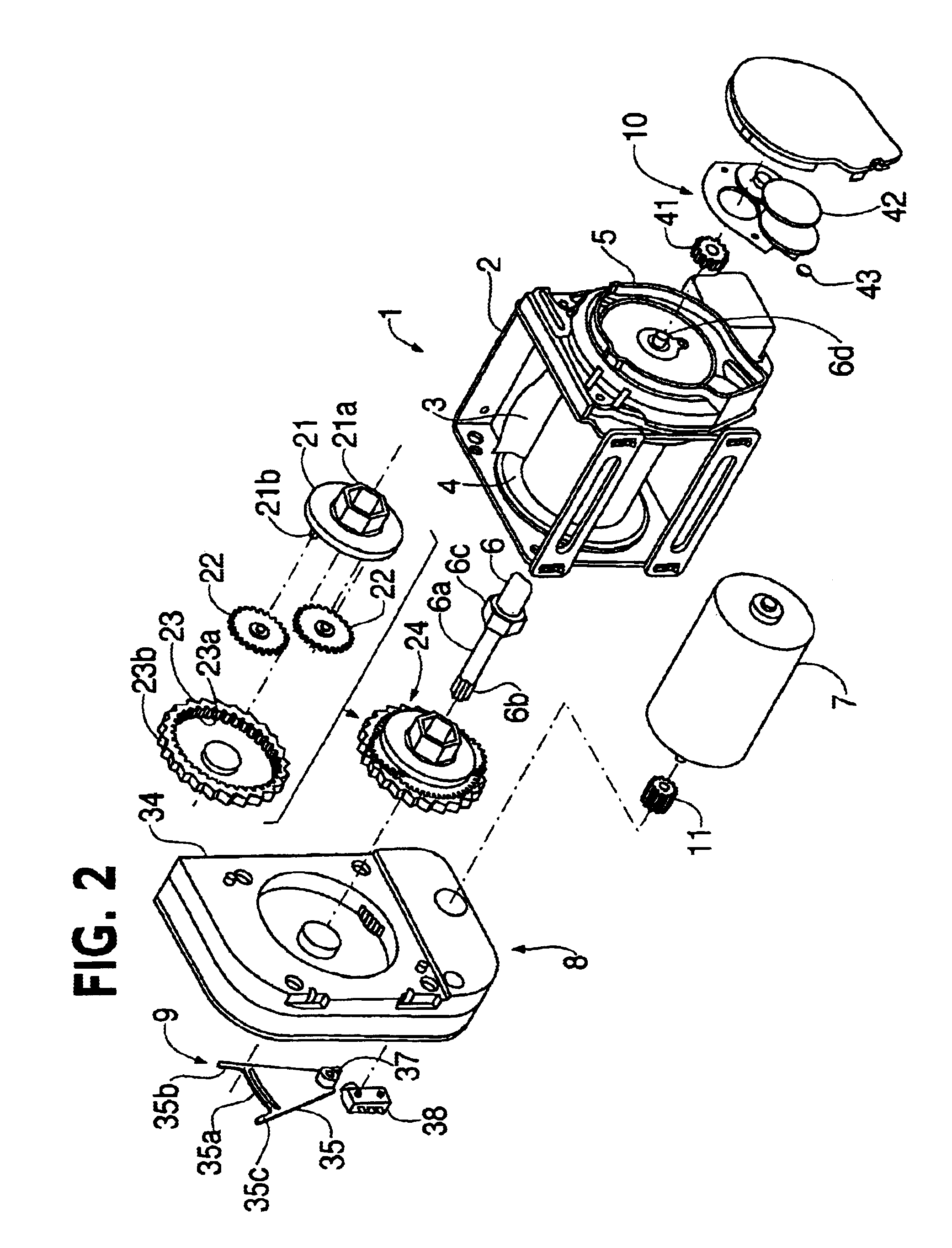
As shown in FIG. 1, the passenger restraining protective system A of this embodiment comprises a seat belt retracting apparatus 1 secured to a car body B and retracts a webbing 3 having a leading end 3a similarly secured to the car body B only by means of the driving force of a motor; a tongue 47 is slidably supported by the webbing 3; and a buckle 48 which is secured to the car body B via a buckle pretensioner (the second pretensioner in the present invention) 51, and permits insertion and engagement of the tongue 47. The same pretensioner as the second pretensioner in the above-mentioned Unexamined Patent Publication may be used as the buckle pretensioner, or a pretensioner disclosed, for example, in Japanese Unexamined Patent Publication No. 5-193443 may also be applicable, the disclosures of which are hereby incorporated by reference. That is, any pretensioner may be selected so far as it a...


PUM


Abstract

The present invention has an object to permit operation of the second pretensioner operating upon determination of a collision, irrespective of operation of the first pretensioner operating upon determination of the possibility of collision. When a vehicle body deceleration is determined not to exceed a set deceleration, possibility of collision with an obstacle is determined on the basis of a relative distance from the obstacle, a relative speed, and a vehicle speed of the subject vehicle. When the possibility of a collision is determined, a motor associated with a retractor is rotated and the webbing is retracted with a large torque until the webbing has the second set belt tension. When the vehicle deceleration is determined to be over a set deceleration, a buckle pretensioner is operated. The buckle is very strongly pulled, and the webbing is set at a third belt tension. The passenger is thus restrained by a large restraining force. At this point, the buckle pretensioner is preferentially operated irrespective of operation of the motor.

Description

This application claims priority to Japanese application no. JP H11-337769, filed Nov. 29, 1999, the disclosure of which is hereby incorporated by reference in its entirety.1. Field of the InventionThe present invention is a passenger restraining protective system for restraining a passenger with a seat belt retracting apparatus that retracts and draws out seat belt webbing. More particularly, the invention is a seat belt retracting apparatus for controlling the belt tension within a predetermined belt tension when the possibility of collision is predicted or when a collision is determined.2. Description of the Related ArtPassenger restraining protective systems having a seat belt retracting apparatus for retracting a webbing generally protect vehicle passengers in an emergency by preventing the passengers from moving away from the seat and restraining them. Such an emergency is a collision where the vehicle undergoes a large deceleration.Japanese Unexamined Patent Publication No. 6...

Claims


Application Information

Patent Timeline
Patent Type & Authority Patents(United States)
IPC IPC(8): B60R22/34B60R22/44B60R22/46B60R21/01B60R21/0134B60R22/48
CPCB60R22/44B60R22/46B60R21/0134B60R2022/4609B60R2022/4666
Inventor FUJII, HIROAKI
Owner JOYSON SAFETY SYST JAPAN KK
Learn More