Variable compression engine

a compression engine and variable technology, applied in the field of combustion engines, can solve the problems of not being able to adapt to the use not improving the combustion process, and not being able to achieve the adaptation of a different fuel without great difficulty, so as to reduce the maximum compression of an internal combustion engine, selectively utilize different fuels, and achieve optimal energy release

Inactive Publication Date: 2007-11-22
SIMS JOHN T
View PDF35 Cites 7 Cited by
  • Summary
  • Abstract
  • Description
  • Claims
  • Application Information

AI Technical Summary

Benefits of technology

[0038] Accordingly, a feature and advantage of the present invention is its ability to adjust compression within the combustion chamber of an internal combustion engine.
[0039] Another feature and advantage of the present invention is its ability to permit an internal combustion engine to selectively utilize different fuels.
[0040] Still another feature and advantage of the present invention is its ability to obtain optimum energy release from fuels having differing compression requirements.
[0041] Yet another feature and advantage of the present invention is its ability to vary compression in response to a variety of sensors and combinations thereof.
[0042] Yet still another feature and advantage of the present invention is its ability to reduce the maximum compression within an internal combustion engine.
[0043] A further feature and advantage of the present invention is its ability to recover fuel vented from the combustion chamber during the compression stroke of an internal combustion engine.

Problems solved by technology

The cost of petroleum fuels, environmental concerns, and fuel supply consistency from politically unstable regions of the world, all cause concern for the viability of gasoline-based fuels.
However, in spite of the benefits, such alternative fuels are not readily introduced into the market due to a lack of equipment that can utilize them efficiently and / or a lack of infrastructure to provide them.
Further compounding the problem is that an engine designed for one type of fuel is not adaptable to utilize a different fuel without great difficulty.
While there are “selective fuel vehicles” available today, and they offer limited ability to utilize alcohols as fuel, they do not improve the combustion process for alcohol, they merely add more fuel (typically by altering the fuel injector timing) to compensate for the lower energy level of alcohols, and, thus, the alcohol fuels are utilized very inefficiently.
Moreover, this reduced efficiency offsets the cost reductions that would otherwise be achieved, and aggravates air, water and soil pollution.
Unfortunately, existing vehicles are limited to use of individual fuels, or use of fuels that are only slight variations of each another, or alternately are inefficient and / or require modifications to run on alternative fuels.
However, alternative renewable fuels, such as ethanol, lack such infrastructure.
Thus, a driver will not purchase a vehicle to run on ethanol if he / she does not know for certain that he / she will be able to obtain ethanol while out and about.
However, this has not heretofore been the norm.
Unfortunately, while engines may be designed to run on ethanol, or mixtures of gasoline and ethanol, current efforts merely design to a new fixed compression and are not directed to attaining an increased efficiency through variability of compression.
If the fuel / air mixture is too hot (from too much compression), an auto-ignition or pre-detonation (knock) may occur that is both detrimental physically to the structure of the engine, and further results in a loss of efficiency.
Unfortunately, the Miller cycle typically disadvantageously requires a supercharger to facilitate the introduction of air into the cylinder through the intake valve.
Unfortunately, Diesel fuels are also typically derived from oil resources, and, thus, do not alleviate the problem of short supplies of oil.
While a modicum of variability of compression can be obtained by selection of the timing of firing of the igniter device, such timing can only offer a limited selectivity of the compression.
Such limitation typically prevents the use of alternative fuels within an engine unless mechanical modifications are made thereto to provide different compression ratios.
Such mechanical modifications are generally extensive and costly.
However, such an approach utilizes discrete levels of compression and precludes continuous variation.
Varying the valve overlap period to change the fuel / air mix will increase or decrease the density of the fuel / air mix, will also result in increased or decreased compression.
However, such overlap (both valves open at the same time) will cause newly introduced fuel to pass out through the exhaust and consequently be wasted.
Again, such an approach can only select between discrete intervals of compression and cannot be externally varied.
As a result of design constraints, such previous devices are limited to selection among fixed ratios of compression and / or rely upon the entry and variation of fuel and / or air admitted to the combustion chamber before the compression portion of the cycle begins.
Thus, previous devices have lacked variation of compression during the compression stroke itself, and further lack the ability to vary the compression ratio by external means.
Due to their lack of variability, such engines are not readily adaptable to changes in fuels or fuel quality.

Method used


Image

  • Variable compression engine
  • Variable compression engine
  • Variable compression engine

Examples


Embodiment Construction

[0051] In describing the preferred and selected alternate embodiments of the present invention, as illustrated in FIGS. 1A-4, specific terminology is employed for the sake of clarity. The invention, however, is not intended to be limited to the specific terminology so selected, and it is to be understood that each specific element includes all technical equivalents that operate in a similar manner to accomplish similar functions.

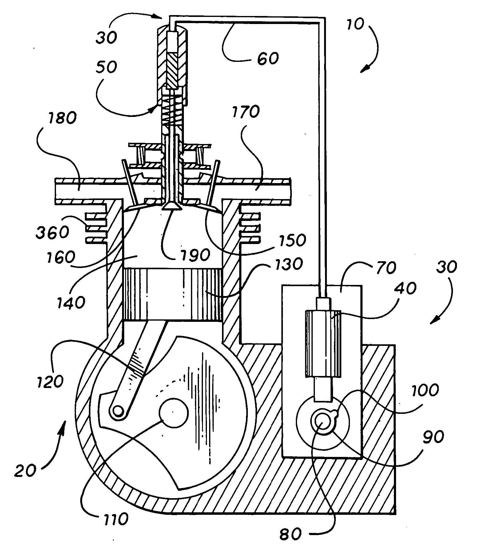
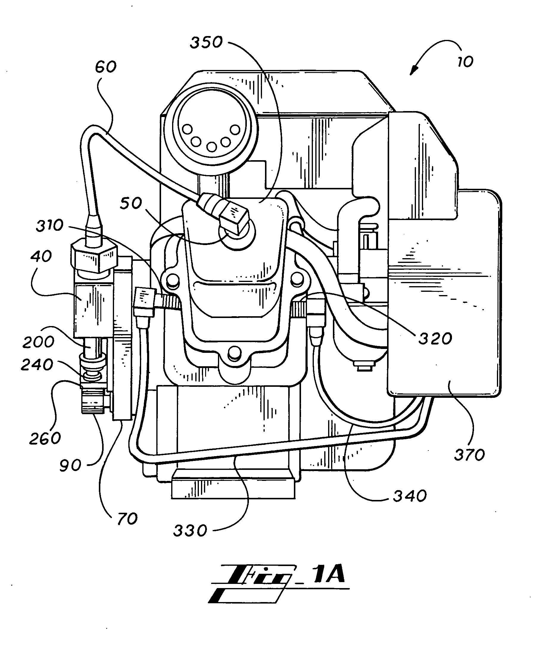
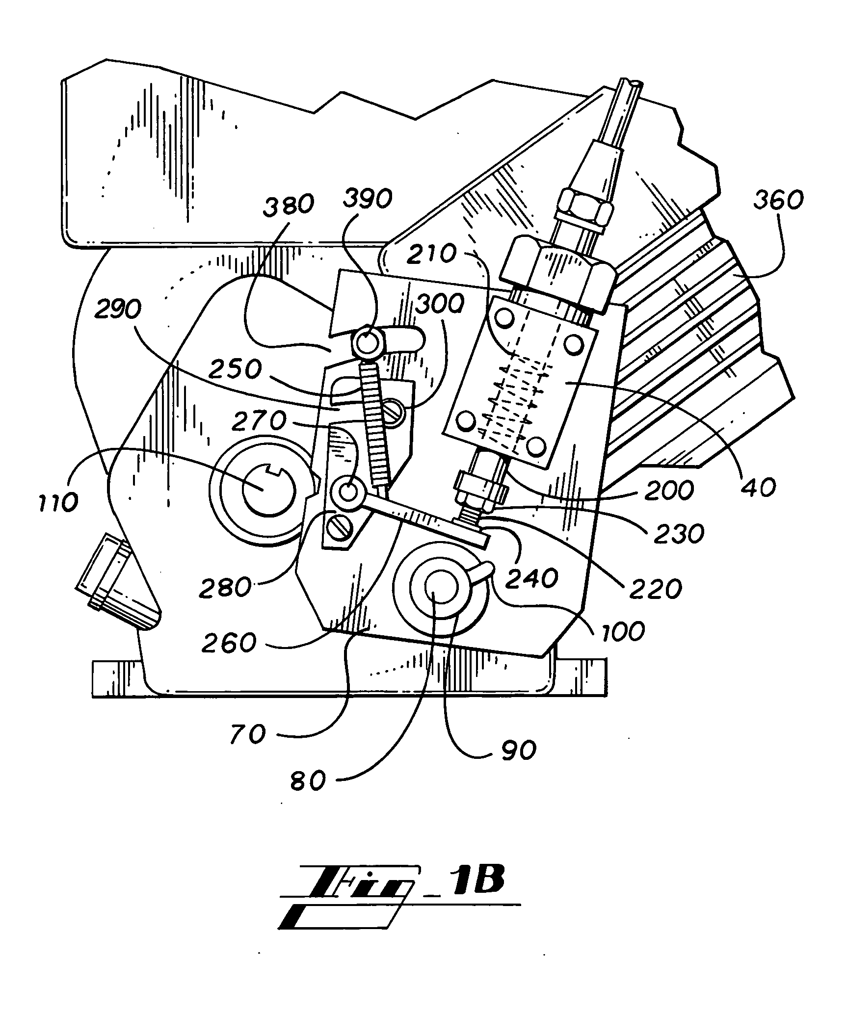
[0052] Referring now to FIGS. 1A-3, the present invention in a preferred embodiment is variable compression engine 10, wherein engine 10 preferably comprises motor 20 and compression relief valve system 30. Motor 20 preferably comprises crankshaft 110, connecting rod, 120, piston 130, combustion chamber 140, valve cover 350, head 360 and camshaft 80, wherein camshaft 80 preferably comprises cam 90 disposed thereon, and wherein cam 90 preferably comprises cam lobe 100. Head 360 preferably comprises compression relief valve 190, relief valve seat 490, intake ...


PUM


Abstract

A variable compression engine has a relief valve disposed in the combustion chamber thereof to reduce compression. The relief valve is open for a portion of the compression stroke of the engine. The open relief valve permits a portion of the fuel / air mixture introduced via the intake valve to leave the combustion chamber and return to the fuel supply or intake manifold via a check valve that prevent flow into the combustion chamber through the relief valve. Timing of the opening and closing of the relief valve is selectable via a cam-operated hydraulically operated by a camshaft rotating once for every two revolutions of the engine's crankshaft, or timing of opening and closing may be achieved by other suitable mechanisms. Additionally, the height of lift of the relief valve can be varied to further adjust compression around a selected relief valve opening point.

Description

TECHNICAL FIELD [0001] The present invention relates generally to combustion engines, and more specifically to a variable compression engine, wherein compression within the combustion chamber is reduced during the compression stroke by opening a relief valve. BACKGROUND OF THE INVENTION [0002] The cost of petroleum fuels, environmental concerns, and fuel supply consistency from politically unstable regions of the world, all cause concern for the viability of gasoline-based fuels. Further, as oil resources dwindle world-wide and demand for oil increases, particularly in developing counties, efforts to utilize other energy resources increase. [0003] Accordingly, more and more countries are turning to alternative fuel sources wherever possible. For example, Brazil (the largest ethanol producer in the world) has substantially converted its vehicle fleet to ethyl alcohol (ethanol) as a fuel stock. Since the United States is the second largest ethanol producer in the world, ready fuel sto...

Claims


Application Information

Patent Timeline
Patent Type & Authority Applications(United States)
IPC IPC(8): F02D13/04F02B75/04F01L9/02F02B75/02F01L9/11
CPCF01L1/08F02D15/00F01L13/06F01L9/021F01L9/11
Inventor SIMS, JOHN T.
Owner SIMS JOHN T
Why Eureka
Try Eureka