Device for reducing impulse noise and method thereof

a technology of impulse noise and impulse noise, applied in the field of image processing, can solve the problems of reducing image quality, inability to correctly determine if the pixel having the biggest (or the least) luminance is impulse noise, and the related art reducing impulse noise method is too simple.

Active Publication Date: 2007-11-15
REALTEK SEMICON CORP
View PDF10 Cites 0 Cited by
  • Summary
  • Abstract
  • Description
  • Claims
  • Application Information

AI Technical Summary

Benefits of technology

[0006]It is therefore one of the objectives of the claimed invention to provide a device and a method for reducing impulse noise of an image signal for solving the above-mentioned problems.
[0007]According to an aspect of the present invention, an impulse noise filtering device is disclosed. The device includes a signal intensity detector, an intensity difference calculator, and a filtering circuit. The signal intensity detector receives an image signal and determines a first pixel having an extreme intensity, and a second pixel having a second extreme intensity of a window of the image frame corresponding to the image signal. The intensity difference calculator determines the intensity difference between the first pixel and the second pixel. The filtering circuit receives the image signal and optionally filters the image signal for reducing the impulse noise according to the intensity difference between the first pixel and the second pixel. According to other aspects of the present invention, the impulse noise filtering device may further comprises at least one or a certain combination of an edge detector, a low-pass filter and a pixel difference detector. The edge detector determines the edge information EP of the image frame, the pixel difference detector determines the difference value of the signal intensity of all pixels of the window, and the low-pass filter filters the image signal and outputs the filtered image signal to the pixel difference detector for improving the accuracy of the pixel difference detector. At least one of the edge information and the difference value assists the filtering circuit in optionally filtering the image signal for reducing the impulse noise, while the intensity difference between the first pixel and the second pixel may be referred or ignored by the filtering circuit.

Problems solved by technology

However, the related art reducing impulse noise method is too simple and not able to correctly determine if the pixel having the biggest (or the least) luminance is impulse noise.
Moreover, the method for utilizing the luminance value of the sub-biggest (or sub-least) pixel to replace the original luminance value of the biggest (or least) pixel will cause decrease the image quality.

Method used


Image

  • Device for reducing impulse noise and method thereof
  • Device for reducing impulse noise and method thereof
  • Device for reducing impulse noise and method thereof

Examples


first embodiment

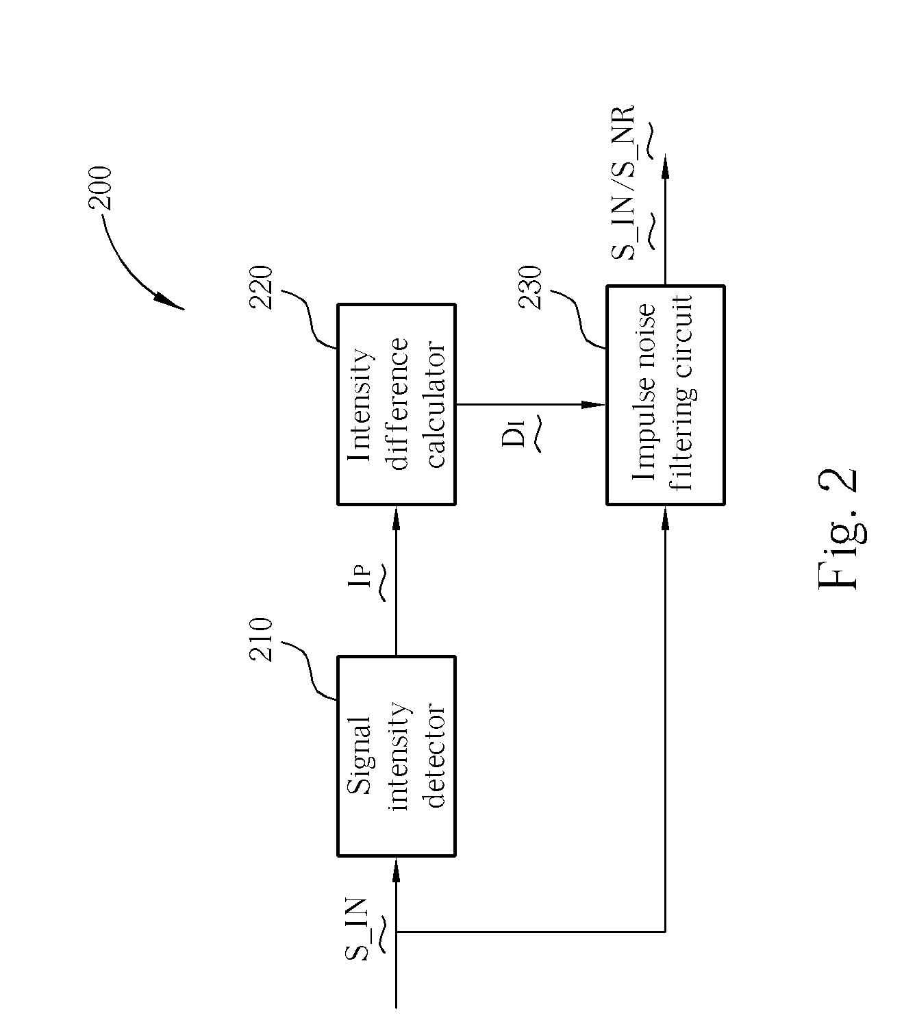
[0022]Please refer to FIG. 2. FIG. 2 is a block diagram of an impulse noise filtering device according to the present invention. The impulse noise filtering device 200 includes a signal intensity detector 210, an intensity difference calculator 220, and an impulse noise filtering circuit 230. The signal intensity detector 210 receives the image signal S_IN which comprises a plurality of image frames, and then determines a first pixel having an extreme intensity (i.e. maximum or minimum intensity) and a second pixel having a second extreme intensity (i.e. sub-maximum or sub-minimum intensity) from all pixels of a window of a specifically image frame. The signal intensity can be the luminance or chrominance of the pixel. The signal intensity detector 210 then sends the signal intensity information IP to the intensity difference calculator 220. The intensity difference calculator 220 determines the intensity difference value DI between the first pixel and the second pixel. The impulse ...

second embodiment

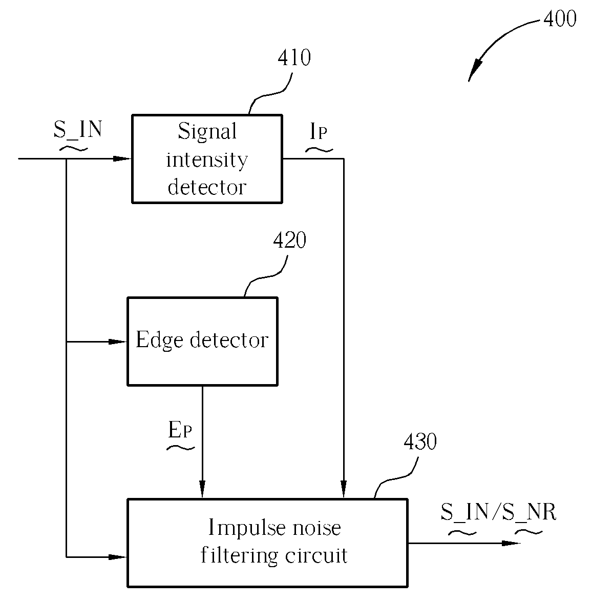
[0025]Please refer to FIG. 4. FIG. 4 is a block diagram of the impulse noise filtering device according to the present invention. The impulse noise filtering device 400 includes a signal intensity detector 410, an edge detector 420, and an impulse noise filtering circuit 430. The function of the signal intensity detector 410 and the signal intensity detector 210 are the same, therefore the details are omitted hereinafter for the sake of brevity. The edge detector 420 is utilized for determining the edge information EP of the target image frame of the image signal S_IN. The edge information EP is utilized for indicating if the present frame detected from the window is a smooth area. If a smooth area is detected, the pixel having an extreme intensity, as determined by the signal intensity detector 410, has a higher possibility of being affected by (i.e., interfered with) as previously detailed earlier in the present disclosure. However, if the present frame detected from the window is...

third embodiment

[0026]Please refer to FIG. 5A. FIG. 5A is a block diagram of the impulse noise filtering device according to the present invention. The impulse noise filtering device 500 includes a signal intensity detector 510, a low-pass filter 520, a pixel difference detector 530, and an impulse noise filtering circuit 540. The function of the signal intensity detector 510 and the signal intensity detectors 210, 410 are the same, therefore the details are omitted hereinafter for the sake of brevity. The pixel difference detector 530 determines the difference value of the signal intensity of all pixels of the window for outputting a pixel difference information DP. In this case if the signal intensity difference between a certain pixel, or some certain pixels, and other pixels is very high, the possibility of impulse noise existing is higher. On the other hand, if the signal intensity difference of all pixels of the window is not high, the possibility of impulse noise existing is lower. In order ...


PUM


Abstract

The present invention provides a device and a method for reducing impulse noise. The device includes a signal intensity detector, an intensity difference calculator, and a filtering circuit. The signal intensity detector receives an image signal and determines a first pixel having an extreme intensity, and a second pixel having a second extreme intensity of a window of the image frame corresponding to the image signal. The intensity difference calculator determines the intensity difference between the first pixel and the second pixel. The filtering circuit receives the image signal and optionally filters the image signal for reducing the impulse noise according to the intensity difference between the first pixel and the second pixel.

Description

BACKGROUND OF THE INVENTION [0001]1. Field of the Invention[0002]The present invention relates to a method for image processing, and more particularly, to a method for reducing impulse noise and the apparatus thereof.[0003]2. Description of the Prior Art[0004]Please refer to FIG. 1. FIG. 1 is a block diagram of a conventional impulse noise filtering device. The impulse noise filtering circuit 110 receives an image signal S_IN, which includes a plurality of image frames. The impulse noise filtering circuit 110 determines a specific image frame by utilizing a window. If the luminance of a certain pixel of the window is bigger (or less) than the luminance of other pixels of the window, the impulse noise filtering circuit 110 will record the location of the biggest (or least) pixel and records the luminance value of the biggest (or least) pixel. Then the impulse noise filtering circuit 110 further determines the pixel with sub-biggest (or sub-least) luminance and records the luminance v...

Claims


Application Information

Patent Timeline
Patent Type & Authority Applications(United States)
IPC IPC(8): G06K9/40
CPCG06T5/002G06T7/0085G06T5/20G06T7/13
Inventor CHAO, PO-WEIOU, HSIN-YING
Owner REALTEK SEMICON CORP
Why Eureka
Try Eureka