Power factor correction power supply

Inactive Publication Date: 2007-11-15
LIN FUYONG +1
View PDF6 Cites 26 Cited by
  • Summary
  • Abstract
  • Description
  • Claims
  • Application Information

AI Technical Summary

Benefits of technology

[0007] In view of the above-described problem, it is one objective of the invention to provide a PFC power supply with improved efficiency and low switching loss.
[0023] When a voltage across the bridge rectifier exceeds a voltage across the storage capacitor circuit, the voltage of the bridge rectifier is applied to the primary winding. At this time the voltage across the bridge rectifier can be regarded to be transferred to the secondary circuit directly without the storage capacitor circuit, therefore time spent on processing energy is reduced, and an efficiency of the PFC converter is improved.

Problems solved by technology

However, the PFC stage increases the cost and the number of devices of the power supply, and therefore the efficiency of the power supply is reduced.
Unfortunately, a common problem with these approaches is an inherent low efficiency due to a fact that energy is processed twice during an energy transferring process, which causes an extremely high switching loss.

Method used


Image

  • Power factor correction power supply
  • Power factor correction power supply
  • Power factor correction power supply

Examples


Embodiment Construction

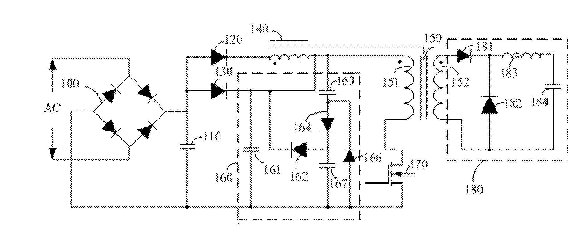
[0027] As shown in FIG. 1, a power factor correction (PFC) power supply of the invention comprises a bridge rectifier 100, a filter capacitor 110, a fly-back diode 120, a forward diode 130, a transformer 150, a storage capacitor circuit 160, and a secondary circuit 180.

[0028] The transformer 150 comprises a fly-back winding 140, a primary winding 151 and a secondary winding 152. The primary winding 151 comprises a first end being connected to a cathode of the forward diode 130, and a second end being connected to a first end of the switch 170. The secondary winding 152 is coupled to the secondary circuit 180.

[0029] The bridge rectifier 100 has an input and an output respectively being connected to input lines and the filter capacitor 110, so as to rectify an alternating current (AC) line voltage to an input voltage.

[0030] The forward diode 130 has an anode being connected to a positive output of the bridge rectifier 100 and a cathode being connected to a first end of the storage ...


PUM


Abstract

Provided herein is a power factor correction (PFC) power supply, comprising: a bridge rectifier having an input and an output, a filter capacitor connected to the output of the bridge rectifier, a transformer having a primary winding, a fly-back winding and a secondary winding, a forward diode, a fly-back diode, a storage capacitor circuit having a valley-fill circuit and a capacitor connected in parallel, and a switch connected between the primary winding and the output of the bridge rectifier. The PFC power supply features improved efficiency and low switching loss.

Description

CROSS-REFERENCE TO RELATED APPLICATIONS [0001] This application is a continuation-in-part of International Patent Application No. PCT / CN2005 / 001570 with an international filing date of Sep. 26, 2005, designating the United States, now pending, and further claims priority benefits to Chinese Patent Application No. 200510006520.4 filed Jan. 19, 2005 and Chinese Patent Application No. 200410080821.1 filed on Jun. 30, 2005. The contents of all of these specifications are incorporated herein by reference.BACKGROUND OF THE INVENTION [0002] 1. Field of the Invention [0003] This invention relates to a power supply, and particularly to a power factor correction power supply. [0004] 2. Description of the Related Art [0005] Conventionally, two-stage converters are widely used to limit harmonics of line currents of electronic equipments to certain levels. A first stage is a power factor correction (PFC) stage comprising an inductor, a rectifier and a transistor, and the transistor is driven by ...

Claims


Application Information

Patent Timeline
IPC IPC(8): H02M3/335
CPCH02M1/34H02M1/4258Y02B70/1491H02M2001/342Y02B70/126H02M3/335H02M1/342Y02B70/10Y02P80/10
Inventor LIN, FUYONGLIN, FUXIANG
Owner LIN FUYONG
Why Eureka
Try Eureka