
Optical storage medium

Inactive Publication Date: 2007-11-08
VICTOR ADVANCED MEDIA CO LTD
View PDF4 Cites 0 Cited by
  • Summary
  • Abstract
  • Description
  • Claims
  • Application Information

AI Technical Summary

Benefits of technology

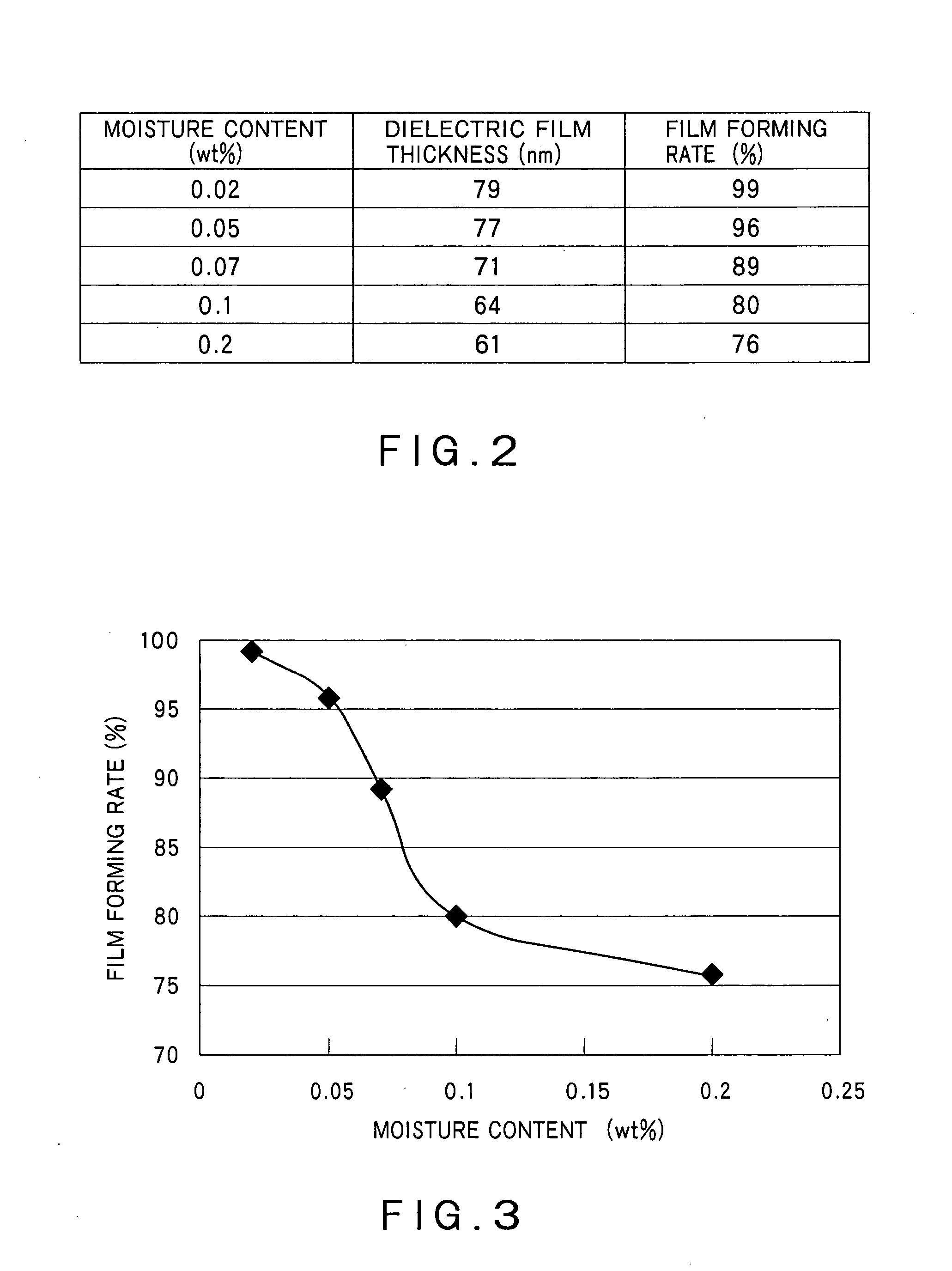
[0013] The purpose of the present invention is to provide an optical storage medium that exhibits higher scratch resistance and excellent antistatic property, produciable at a higher film-forming rate for each film formed on a surface of a substrate after a hard coat is formed on the other surface, with increased productivity.

Problems solved by technology

Substrates made of such a thermoplastic resin, however, have low surface hardness, thus prone to scratch and susceptible to static electricity.
Optical storage media having a substrate made of such a thermoplastic resin could suffer errors in recording or reproduction when daily used because of scratches, dust due to static electricity, etc.
An optical disc with a dielectric film having a thickness beyond a margin of ±5% of designed thickness cannot meet the requirements of reflectivity, modulation, overwrite characteristics, etc.
Hard-coat formation after a dielectric film, however, lowers yields than before a dielectric film, due to dust on a substrate during the film forming process.
A longer dielectric-film forming time lowers production efficiency.
Moreover, production efficiency lowers when a dielectric-film forming time is extended.

Method used


Image

  • Optical storage medium
  • Optical storage medium
  • Optical storage medium

Examples


embodiment sample e1

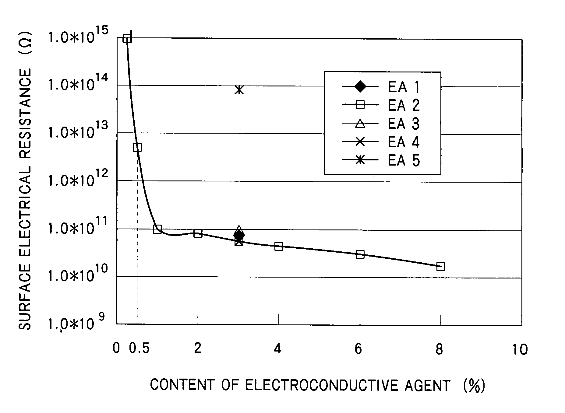
[0058] The hard coat layer 1H was formed with an antistatic hard coat agent containing 3% by weight of an ionic liquid, prepared by fully mixing 97% by weight of the hard coat agent of the embodiment and 3% by weight of an ionic liquid, N,N-diethyl-N-methyl (2-methoxyethyl) ammonium bis (trifluoromethanesulfonyl) imide (referred to as an electroconductive agent EA1, hereinafter), as an antistatic agent.

[0059] This antistatic hard coat agent had a moisture content of 0.02% by weight, with almost no increase in moisture content due to addition of the ionic liquid.

[0060] Each ratio (% by weight) of the hard coat agent and the electroconductive agent is the ratio of the corresponding agent to the total weight of the antistatic hard coat agent, in this embodiment.

[0061] The antistatic hard coat layer 1H of this embodiment is formed with the antistatic hard coat agent applied on the substrate 1 and hardened with irradiation of ultraviolet rays, thus almost no decrease in moisture, as d...

embodiment sample e2

[0066] The hard coat layer 1H was formed with an antistatic hard coat agent containing 97% by weight of the hard coat agent of the embodiment and 3% by weight of an ionic liquid, trioctylmethyl ammonium bis (trifluoromethanesulfonyl) imide (referred to as an electroconductive agent EA2, hereinafter). The antistatic hard coat agent had a moisture content of 0.02% by weight.

[0067] The embodiment sample E2 coated with the hard coat layer 1H, as described above, exhibited electrical resistances R1 and R2 both lower than 1×10¹⁴Ω on the layer 1H, thus giving a sufficient antistatic effect, and almost no change in appearance changes A1 and A2.

embodiment sample e3

[0068] The hard coat layer 1H was formed with an antistatic hard coat agent containing 97% by weight of the hard coat agent of the embodiment and 3% by weight of an ionic liquid, 1-ethyl-3-methylimidazodium tetrafluoromethane sulfonate (referred to as an electroconductive agent EA3, hereinafter). The antistatic hard coat agent had a moisture content of 0.02% by weight.

[0069] The embodiment sample E3 coated with the hard coat layer 1H, as described above, exhibited electrical resistances R1 and R2 both lower than 1×10¹⁴Ω on the layer 1H, thus giving a sufficient antistatic effect, and almost no change in appearance changes A1 and A2.


PUM


Abstract

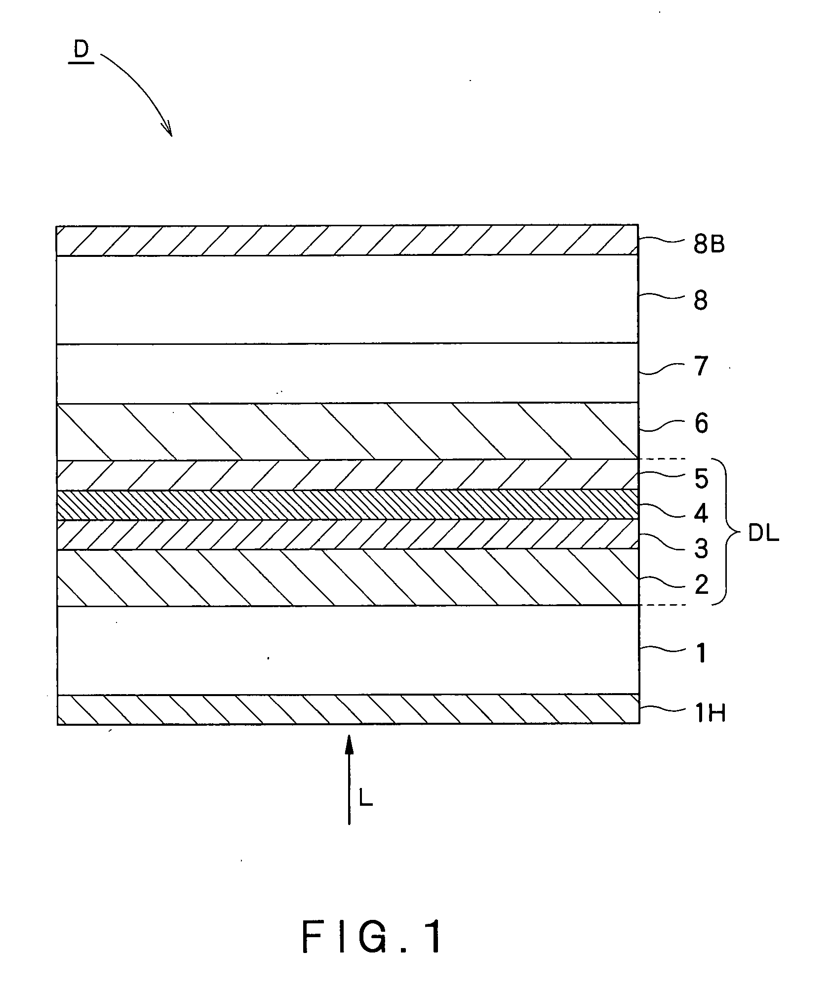
An optical storage medium has a substrate having a first surface and a second surface on both sides. Formed on the first substrate is a layer of at least a dielectric film, a recording film and a reflected film. Formed on the second surface is a hard coat layer that includes a hardened antistatic hard coat agent containing a hard coat agent and an ionic liquid as an antistatic agent.

Description

CROSS-REFERENCE TO RELATED APPLICATIONS [0001] This application is based on and claims the benefit of priority from the prior Japanese Patent Application No. 2006-120618 filed on Apr. 25, 2006, the entire content of which is incorporated herein by reference. BACKGROUND OF THE INVENTION [0002] The present invention relates to an optical storage medium having a substrate with a hard coat agent applied thereon. The invention, particularly, relates to an optical storage medium having a substrate with an antistatic hard coat agent applied thereon. [0003] Optical storage media for which data are recorded or reproduced, such as, DVD-RW, have widely been used in a variety of fields. Substrate materials for such optical storage media are usually thermoplastic resins, such as, polymethylmethacrylate, polycarbonate, etc., for their excellent formability and optical characteristics. [0004] These thermoplastic resins are excellent in mass producibility, formability and cost performance. Polycarb...

Claims


Application Information

Patent Timeline
IPC IPC(8): B32B7/00
CPCG11B7/00454G11B7/2542G11B7/24056
Inventor HIRAMA, MAKOTO
Owner VICTOR ADVANCED MEDIA CO LTD
Learn More