
Method for deblurring images using optimized temporal coding patterns

a temporal coding pattern and image technology, applied in the field of processing images, can solve the problems of reducing whole-image blur, unable to correct the blur of moving occluders, and deconvolution can produce strong noisy artifacts, so as to reduce whole-image blur and strong noisy artifacts

Active Publication Date: 2007-11-08
MITSUBISHI ELECTRIC RES LAB INC
View PDF2 Cites 278 Cited by
  • Summary
  • Abstract
  • Description
  • Claims
  • Application Information

AI Technical Summary

Benefits of technology

[0025] Conventional cameras leave the shutter open during the exposure time and attempt to deblur the image with image stabilizing and / or deconvolution techniques. Such techniques can reduce whole-image blur due to camera motion, but cannot correct blur from moving occluders. In addition, deconvolution can produce strong noisy artifacts.
[0026] The embodiments of the invention minimize motion blur in images acquired of a scene by a camera. Rather than leaving the shutter open for the entire exposure time, the shutter is rapidly ‘fluttered’. That is, the shutter is opened and closed in an irregular temporal sequence to produce an encoded image.
[0029] It should be noted that the modulating, sampling, and decoding techniques described herein can also be with other energy fields such as ultrasound and sonar sensing. There, the sensed signal is low-pass filtered due to limitations of the device or because the sonar device moved. By using a temporal sampling code, the attenuation of high frequency components can be reduced.

Problems solved by technology

Such techniques can reduce whole-image blur due to camera motion, but cannot correct blur from moving occluders.
In addition, deconvolution can produce strong noisy artifacts.

Method used


Image

  • Method for deblurring images using optimized temporal coding patterns
  • Method for deblurring images using optimized temporal coding patterns
  • Method for deblurring images using optimized temporal coding patterns

Examples


Embodiment Construction

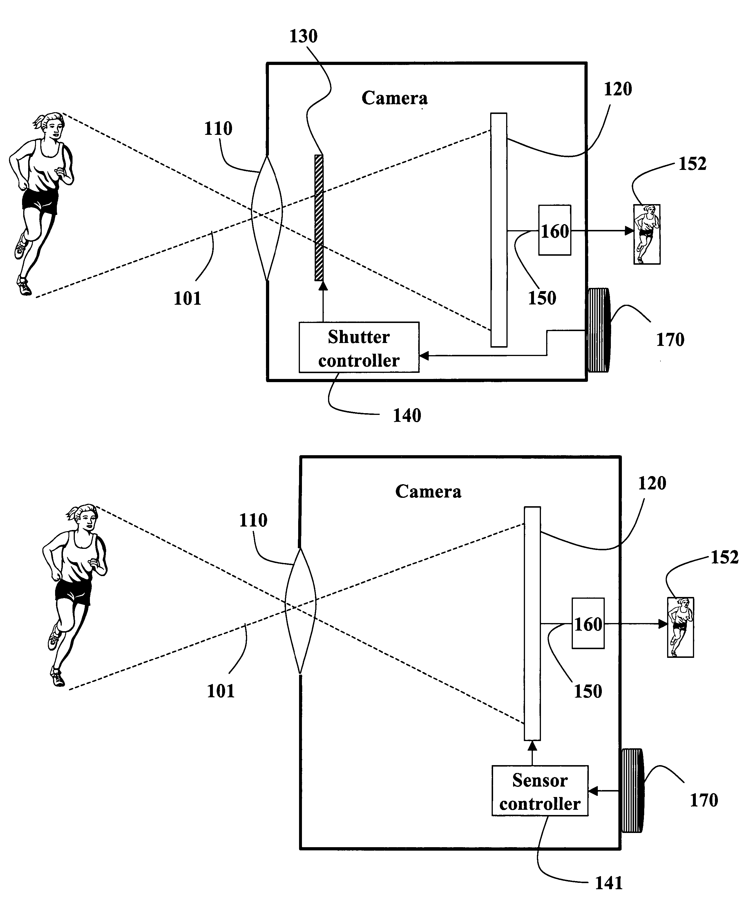
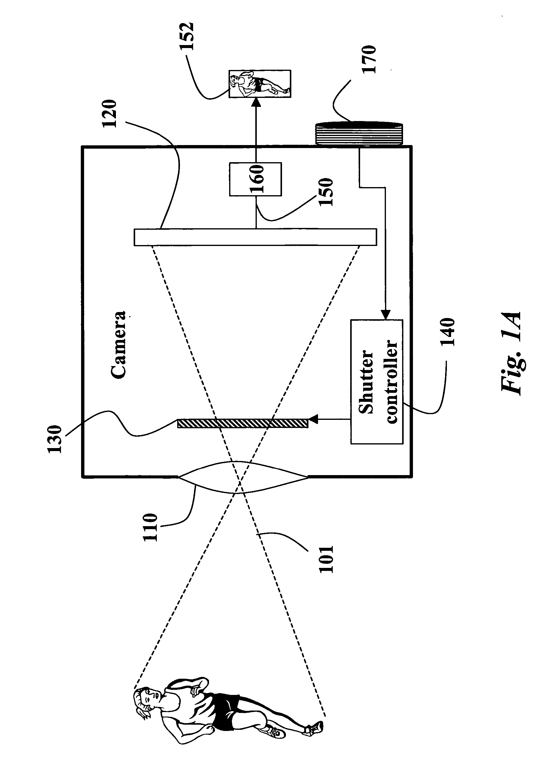
[0044]FIGS. 1A, 1B and 1C show simplified schematics of a deblurring camera according to embodiments of our invention. The camera includes a lens 110, a solid state image sensor 120, a shutter 130, and a shutter controller 140. In a preferred embodiment, the camera is a digital camera, and the sensor includes an array of pixels. The pixels can include RGB pixels interleaved in a Bayer grid. The camera can be a single photosensor. The camera can also be a digital video camera that produces a sequence of images or frames. An input image is produced on line 150 as a digital signal.

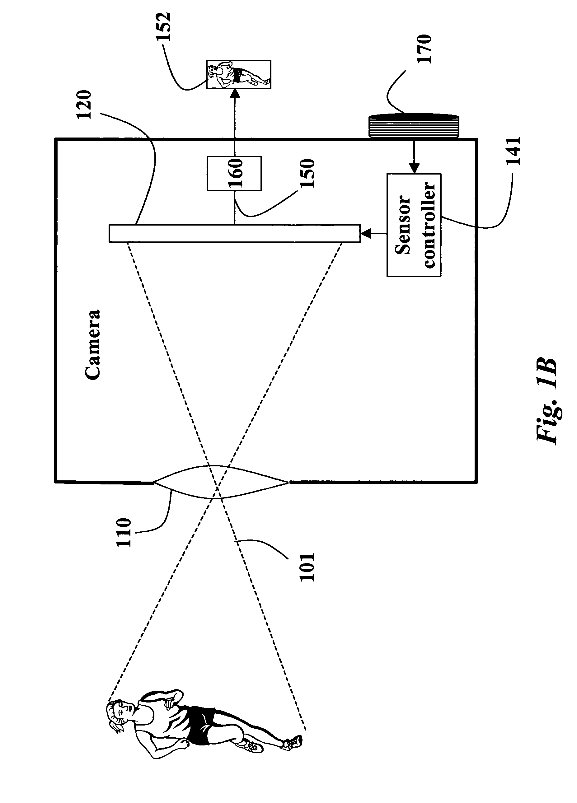
[0045] In the embodiment shown in FIG. 1B, the shutter functionality of FIG. 1A is implemented by a sensor controller 141 that can temporally turn the sensor 120 on and off while acquiring and integrating an input energy field 101. The energy field can be any type of electromagnetic radiation, e.g., visible or infrared light, or acoustic radiation, e.g., ultrasound and sonar.

[0046] In the embodiment shown i...


PUM


Abstract

A method and system deblurs images acquired of a scene by a camera. A light field acquired of a scene is modulated temporally according to a sequence of ons and offs. An optimal coding pattern is selected. The modulated light field is integrated by a sensor of a camera during an exposure time to generate an encoded input image. The encoded input image is decoded according to a pseudo-inverse of a smearing matrix to produce a decoded output image having a reduced blur.

Description

RELATED APPLICATION [0001] This application is related to U.S. patent application Ser. No. ______ entitled “Method and Apparatus for Deblurring Images” and co-filed with this application by Ramesh Raskar on May 5, 2006.FIELD OF THE INVENTION [0002] This invention relates generally to processing images, and more particularly to deblurring images using optimized temporal coding patterns. BACKGROUND OF THE INVENTION [0003] Movement is an important aid to human visual perception. It helps us see, interpret and better understand our surroundings. Despite its usefulness to human viewers, motion is often the bane of photography. The clearest, most detailed image requires a perfectly stationary camera and scene. This is extremely difficult for amateur photography in natural settings. [0004] Conventional cameras include several manual or automatic controls to deal with various camera and scene parameters, such as focus depth and exposure time. However, the solutions for dealing with motion i...

Claims


Application Information

Patent Timeline
IPC IPC(8): G03B17/00
CPCH04N5/23248H04N5/23258H04N5/238H04N5/2353H04N5/2329H04N23/68H04N23/689H04N23/6812H04N23/73H04N23/75
Inventor RASKAR, RAMESHTUMBLIN, JACKAGRAWAL, AMIT
Owner MITSUBISHI ELECTRIC RES LAB INC
Learn More