
Apparatus and method for angular colorimetry

a technology of angular colorimetry and apparatus, applied in the field of apparatus and method of angular colorimetry, can solve the problems of inability to adjust the angle of viewing, the reflection color of such stacks can change quite perceptibly with viewing angle, and the color change can be quite dramatic and unacceptable, and achieve the effect of cost-effectiveness

Active Publication Date: 2007-11-08
CARDINAL CG
View PDF2 Cites 33 Cited by
  • Summary
  • Abstract
  • Description
  • Claims
  • Application Information

AI Technical Summary

Benefits of technology

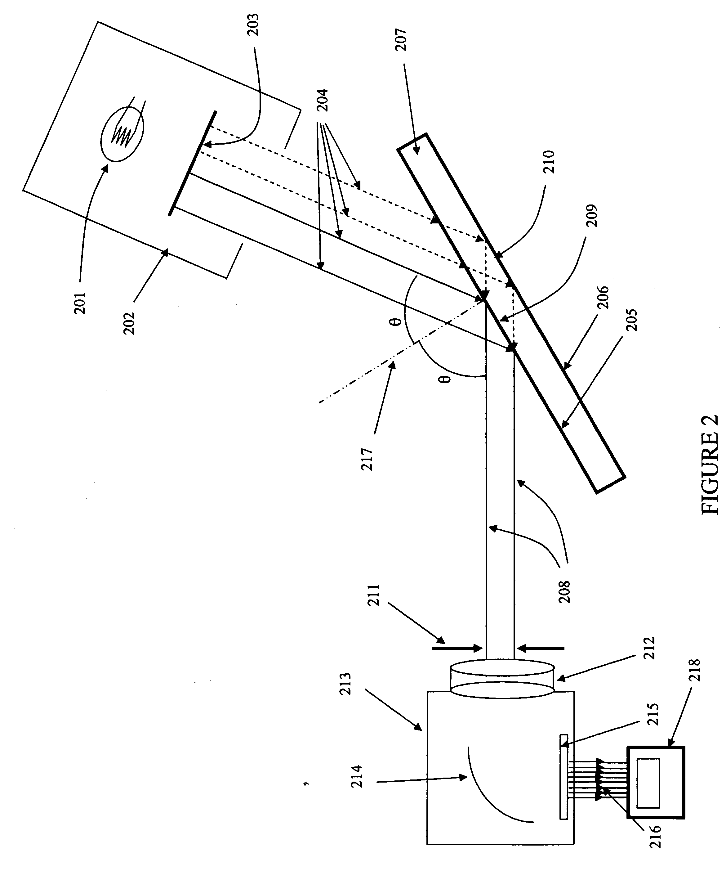
The present invention provides a spectral reflectance apparatus that can measure the reflectance properties of an object with front and back reflecting surfaces. The apparatus includes a sample stage, a light source, a detector, and a positioning device. The method involves illuminating the object at varying angles of incidence, collecting reflected light from the front and back reflecting surfaces at respective specularly reflected angles, wavelength resolving the reflected light into a color spectrum, and analyzing the intensity of the color spectrum as a function of wavelength. The technical effects of the invention include providing a cost-effective and rugged solution for measuring the angular color variation data required by the glass coating and similar industries, as well as a quality control tool for coating or architectural window development.

Problems solved by technology

Unfortunately, for reasons well known to the designers of multilayer coating stacks, the reflectance color of such stacks can change quite perceptibly with viewing angle.
If due attention is not paid to this aspect the color change can be quite dramatic and unacceptable.
The chief disadvantage of this method is that it relies on subjective judgment of a color match which is often perceived differently by different inspectors in part because about 5% of the male population has some red / green color vision deficiency.

Method used


Image

  • Apparatus and method for angular colorimetry
  • Apparatus and method for angular colorimetry
  • Apparatus and method for angular colorimetry

Examples


example 1

[0058] Two low emissivity stack designs are given in the following table along with the layer thickness change from Design A to Design B.

Layer Thickness in nanometersA to BThicknessLayer MaterialDesign ADesign BDifferenceSiAlOxNy24.626.21.6NiCr metal5.54.8−0.6NiCrOx1.01.00.0Ag13.013.00.0ZnO6.06.00.0SiAlOxNy56.060.04.0NiCr metal8.08.00.0NiCrOx2.02.00.0Ag10.510.50.0ZnO10.010.00.0SiAlOxNy12.315.12.8Glass Substrate3.23.20.0(thickness in mm)

[0059] When single light, normal incidence color readings are taken on these designs, both show similar numbers and either would be acceptable in the marketplace.

Normal Incidence Color (8.5 degrees)a*b*L*Design ATransmission−3.26−2.9070.25Glass Side−1.85−3.7940.77ReflectionCoated Side−8.370.8326.42ReflectionDesign BTransmission−3.04−2.0472.14Glass Side−1.79−3.9041.23ReflectionCoated Side−10.315.0226.57Reflection

[0060] When glass side reflection color readings at various angles are taken from these same coatings, Design A is shown to be red in appe...


PUM

PropertyMeasurementUnit
distanceaaaaaaaaaa
angle of acceptanceaaaaaaaaaa
angle of incidenceaaaaaaaaaa

Abstract

An apparatus for measuring the reflectance properties of an object having a front reflecting surface and at least one back reflecting surface. The apparatus includes a sample stage for placement of the object, a light source, a detector configured to detect reflected light from the object, and a positioning device configured to provide a plurality of angular positions for the light source and the detector relative to the object on the sample stage such that incident light on the object is specularly reflected towards the detector and the reflected light received at the detector includes a front surface reflection from the object and at least one back surface reflection from the object. The method includes illuminating the object at varying angles of incidence, collecting reflected light from the front and back reflecting surfaces of the object at respective specularly reflected angles, wavelength resolving the reflected light into a color spectrum, and analyzing an intensity of the color spectrum as a function of wavelength.

Description

FIELD OF THE INVENTION [0001] The invention relates to an apparatus and method for angular colorimetry with use in fields such as architectural glass panels. BACKGROUND OF THE INVENTION [0002] Energy efficient coatings are becoming increasingly used on architectural and automotive glass and in other applications. Their use is progressively mandated by government standards and the coatings are becoming quite sophisticated as the specifications they must meet for control of solar transmission, infrared transmission and heat retention become ever more demanding. [0003] Indeed, in order to meet the demands for improved energy efficiency, it has been found necessary to deposit at least some of the coatings as multilayer interference stacks. (ref. Coated Glass Applications and Markets, R. Hill and S. Nadel, published by BOC Coating Technology, Fairfield Calif., 1999, the entire contents of which are incorporated herein by reference). These stacks have a specific reflectance color when vie...

Claims


Application Information

Patent Timeline
Patent Type & Authority Applications(United States)
IPC IPC(8): G01N21/47
CPCG01N21/55G01N2021/8427G01N2021/575G01N2021/558
Inventor SIECK, PETER ALLENGUTHRIE, JOE EARLEMASCHWITZ, PETER ALANBURTON, CLIVE HILTONSINGHAVARA, VANHLACKY LUCKYMARSHALL, BRYAN RICHARD
Owner CARDINAL CG
Learn More