
Novel aesthetics in surfaces employing deformation and magnetic means

a technology of deformation and magnetic means, applied in the direction of magnetic materials, magnetic bodies, coatings, etc., can solve the problems of not producing certain categories of decorative patterns, certain decorative patterns and/or decorative patterns that have not been incorporated into solid surface materials before, and achieving the effect of reducing the number of decorative patterns

Inactive Publication Date: 2007-11-01
EI DU PONT DE NEMOURS & CO
View PDF11 Cites 8 Cited by
  • Summary
  • Abstract
  • Description
  • Claims
  • Application Information

AI Technical Summary

Benefits of technology

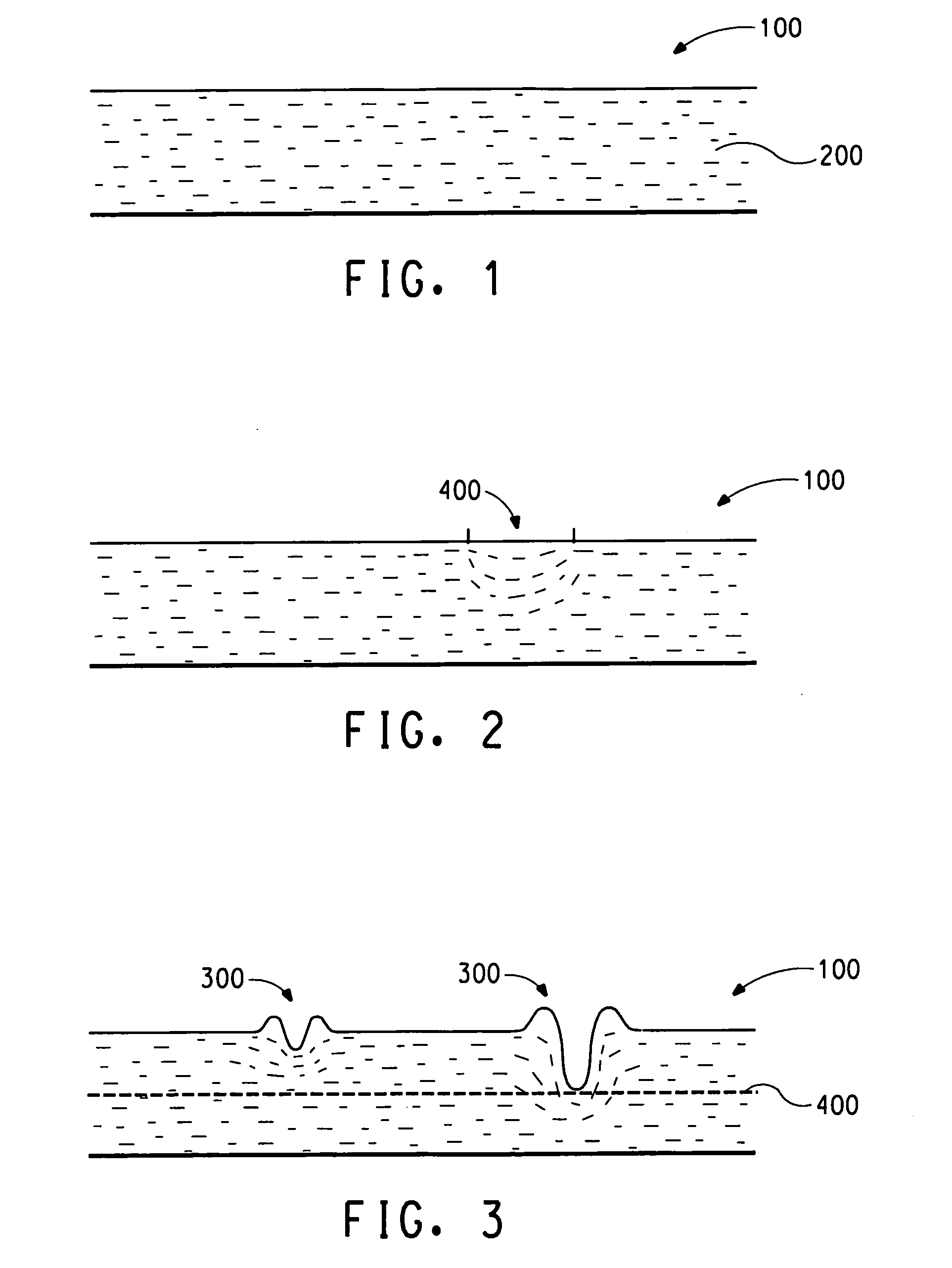
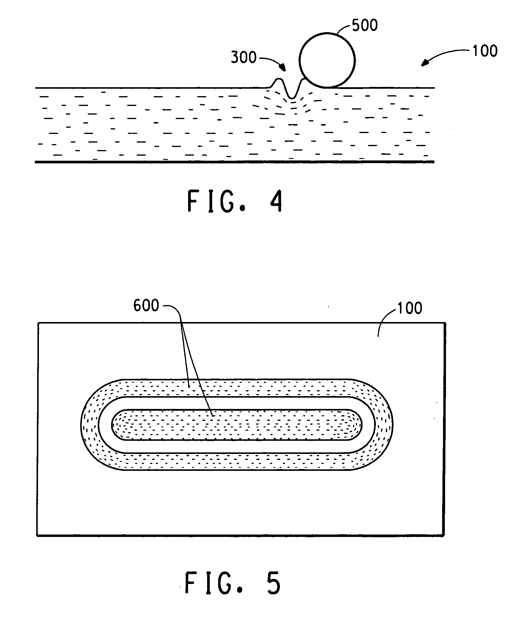
[0014] In another embodiment of the process of the invention, a decorative pattern in a surface of a solid surface material containing magnetic anisotropic particles is formed by the steps of orienting at least a majority of the magnetic anisotropic particle in a flowable solid surface material, indenting a plurality of surface areas in the flowable solid surface material to disrupt the orientation of the anisotropic particle at indented surface areas, inducing a magnetic field in a portion of surface areas of the flowable solid surface material to change the orientation of magnetic particles in the magnetic field, smoothing the surface of the flowable solid surface material having indented surface areas, and solidifying the flowable solid surface material.

Problems solved by technology

However, due to limitations of feasibility and / or practicality, certain decorative patterns and / or categories of decorative patterns have not previously been incorporated in solid surface materials.
They do not produce certain categories of decorative patterns not dependent on combinations of different colors.

Method used


Image

  • Novel aesthetics in surfaces employing deformation and magnetic means
  • Novel aesthetics in surfaces employing deformation and magnetic means

Examples


example 1

[0033] The following ingredients were weighed out and mixed:

620gmAlumina Trihydrate (ATM)318.13gmSirup (24% PMMA in MMA)39.58gmMMA Monomer3.03gmTrimethylol propane trimethacrylate (TRIM)8.49gmPMA 25 paste (t-butylperoxy maleic acid)1.56gmDioctyl sodium sulfosuccinate0.68gm85% phosphated hydroxyethylmethacrylate inbutyl methacrylate9.96gmstainless steel flake with magneticcharacteristics

at a temperature of 28 degrees C. After mixing for 1 minute, 0.91 grams of distilled water was added to the mixture. The mixture was then evacuated under vacuum (24-25 in Hg) using a pump and a suitable condensing vapor trap. After mixing and evacuating for approximately 3 minutes, 2.58 grams of calcium hydroxide slurry (34% in sirup) and 1.33 grams of ethylene glycol dimercaptoacetate were added using syringes. After 45 seconds of additional mixing and evacuation, the mixture was poured into a container of square design to form a layer of approximately 0.5-inch thickness. The container had a 0.040...

example 2

[0036] A casting mixture was prepared according to the process of Example 1. Immediately after pouring the mixture into the stainless steel container the casting was then traversed with a magnetic field, creating a linear pattern. The magnetic field was created with two electromagnets with 0.5-inch diameter by 1.27-inch length inner cores made of 1215 steel. The electromagnet coils consisted of 4,000 turns, a coil winding density of approximately 3200 turns / inch, and a coil resistance of 150 ohms. The coil outer diameter was approximately 1 and 5 / 16-inches. The centerlines of the cylindrical electromagnets were aligned and the ends of the cores were spaced 0.060-inches from the bottom of the casting container and from the top of the poured casting. The electromagnet coils were wired with opposite polarity and powered with 0.5 amperes of direct current. The electromagnets were positioned around the casting, the power was turned on, and the electromagnets were traversed across the cas...


PUM

PropertyMeasurementUnit
Surfaceaaaaaaaaaa
Deformation enthalpyaaaaaaaaaa
Aspect ratioaaaaaaaaaa

Abstract

Polymeric or polymerizable material with oriented decorative anisotropic particles is subjected to deformation and magnetic fields that reorient the decorative particles. The result is an aesthetic patterned appearance.

Description

BACKGROUND OF THE INVENTION [0001] 1. Field of Invention [0002] This invention relates to a process for producing a decorative surfacing material by selective orientation of decorative fillers by magnetic and impact means. [0003] 2. Description of the Related Art [0004] The preferred use for the process of this invention is the production of a decorative solid surface material. As employed herein, a solid surface material is understood in its normal meaning and represents a uniform, non-gel coated, non-porous, three dimensional solid material containing polymer resin and particulate filler, such material being particularly useful in the building trades for kitchen countertops, sinks, wall coverings, and furniture surfacing wherein both functionality and an attractive appearance are necessary. A well-known example of a solid surface material is Corian® produced by E. I. DuPont de Nemours and Company. A number of design aesthetics are heretofore known in solid surface materials, such ...

Claims


Application Information

Patent Timeline
IPC IPC(8): B05D3/12H01F1/00
CPCB29C59/007B29C59/16B29C70/64B29K2105/203H01F41/16B29K2995/0008B44C1/005H01F1/20B29K2995/0003
Inventor OLSON, BARRY D.PAPLHAM, WILLIAM PATRICK
Owner EI DU PONT DE NEMOURS & CO
Learn More