Semiconductor element mounting board and optical transmission module
a technology of optical transmission module and semiconductor element, applied in the field of optical transmission module, can solve the problems of increasing the number of components to be mounted and the mounting area, reducing the size of the transceiver and its production cost, and creating unnecessary gain (peaking), so as to reduce the output waveform of an optical modulator, reduce the small signal reflection coefficient, and suppress the effect of peaking in small signal passage characteristics
- Summary
- Abstract
- Description
- Claims
- Application Information
AI Technical Summary
Benefits of technology
Problems solved by technology
Method used
Image
Examples
embodiment 1
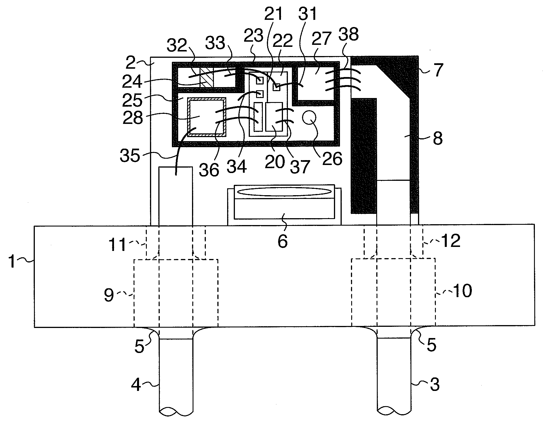
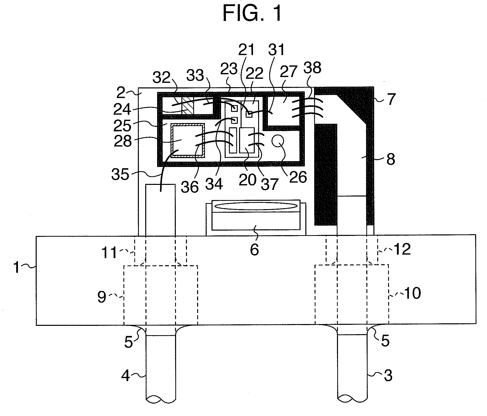
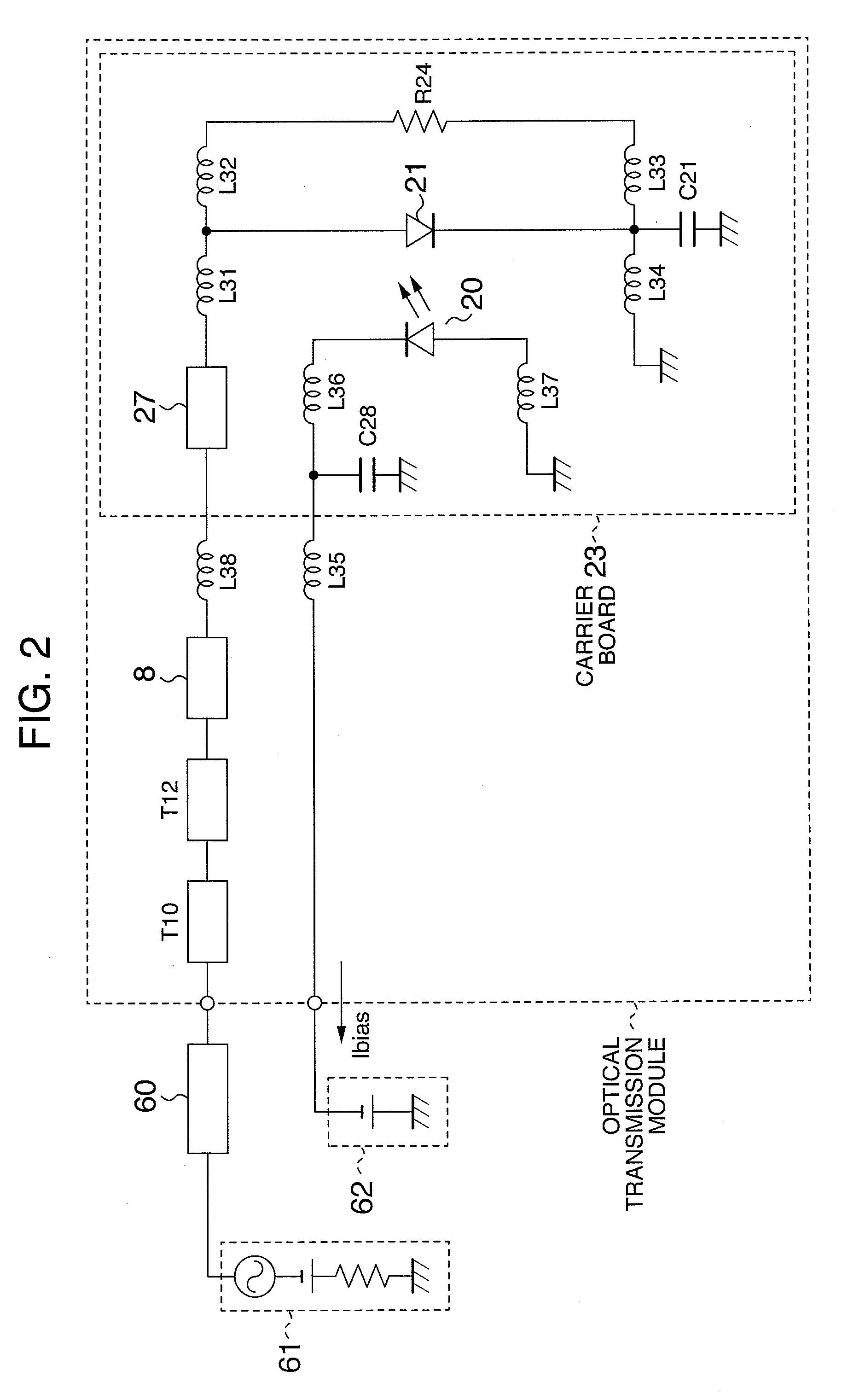
[0042]The first embodiment of the invention will be explained with reference to FIGS. 1 through 3 and FIGS. 9 through 13.
[0043]FIG. 1 is a structural view that shows main portions of an optical transmission module according to this embodiment, FIG. 2 is a main circuit diagram of the optical transmission module, and FIG. 3 is a detailed view of a carrier board portion for mounting optical semiconductor elements. FIG. 9 is a graph showing the relation between a frequency and electric-optical small signal passage characteristic S21 of the optical transmission module, FIG. 10 shows an optical output waveform of the optical transmission module, and FIGS. 11 through 13 are graphs respectively showing excessive gain characteristics, 3 dB band characteristics and input reflection characteristics S11 of the optical transmission module when inductance of a bonding wire to be connected to an optical modulator element is changed.
[0044]First, the construction of the optical transmission module w...
embodiment 2
[0082]The second embodiment of the invention will be explained with reference to FIGS. 4 to 6 and FIGS. 19 to 22.
[0083]FIG. 4 is a structural view that shows main portions of an optical transmission module according to this embodiment. FIG. 5 is a main circuit diagram of the optical transmission module. FIG. 6 is a detailed view of a carrier board portion. FIG. 19 is a graph that shows input reflection characteristics S11 of this embodiment. FIG. 20 is a graph that shows small signal passage characteristics S21.
[0084]As shown in FIGS. 4 and 6, the main differences from the embodiment 1 reside in that the arrangement of the anode and cathode of the surface electrodes of the semiconductor chip 122 is reversed to the right and left and that the input transfer line 127 is extended to a portion below the optical modulator element 21. Independent back electrodes are disposed below the optical modulator element 121 and the semiconductor laser diode element 120 on the back of the semiconduc...
embodiment 3
[0091]The third embodiment of the invention will be explained with reference to FIGS. 7 and 8.
[0092]FIG. 7 is a structural view that shows main portions of an optical transmission module according to this embodiment. FIG. 8 is a main circuit diagram of the optical transmission module. The main difference from the second embodiment described above resides in that the optical modulator element 21 is driven by differential electric modulation signals.
[0093]The construction of the optical transmission module will be first explained with reference to FIG. 7. The optical transmission module uses a CAN type package casing as its casing. Reference numeral 1 denotes a metal stem and reference numeral 2 denotes a metal seat for mounting a main portion. Circular cylindrical lead pins 3 and 4 are provided to the metal stem 1 through through-holes 209 and 210 and are fixed by sealing glass 5. Relay boards 205 and 207 and a carrier board 223 are mounted onto the metal seat 2. A transfer line 206 ...
PUM
| Property | Measurement | Unit |
|---|---|---|
| impedance | aaaaa | aaaaa |
| diameter | aaaaa | aaaaa |
| resistance | aaaaa | aaaaa |
Abstract
Description
Claims
Application Information
 - R&D
- Intellectual Property
- Life Sciences
- Materials
- Tech Scout
- Unparalleled Data Quality
- Higher Quality Content
- 60% Fewer Hallucinations
Browse by: Latest US Patents, China's latest patents, Technical Efficacy Thesaurus, Application Domain, Technology Topic, Popular Technical Reports.
© 2025 PatSnap. All rights reserved.Legal|Privacy policy|Modern Slavery Act Transparency Statement|Sitemap|About US| Contact US: help@patsnap.com


