
Placement-Driven Physical-Hierarchy Generation

a physical hierarchy and hierarchy technology, applied in the field of integrated circuit design, can solve the problems of increasing signal delay, introducing an extra level of complexity over flat design, and routing deviating from their optimal shortest path, so as to improve the initial partition from initial partition generation, reduce the size of the hypergraph, and high placement affinity

Inactive Publication Date: 2007-10-18
MAGMA DESIGN AUTOMATION
View PDF3 Cites 68 Cited by
  • Summary
  • Abstract
  • Description
  • Claims
  • Application Information

AI Technical Summary

Benefits of technology

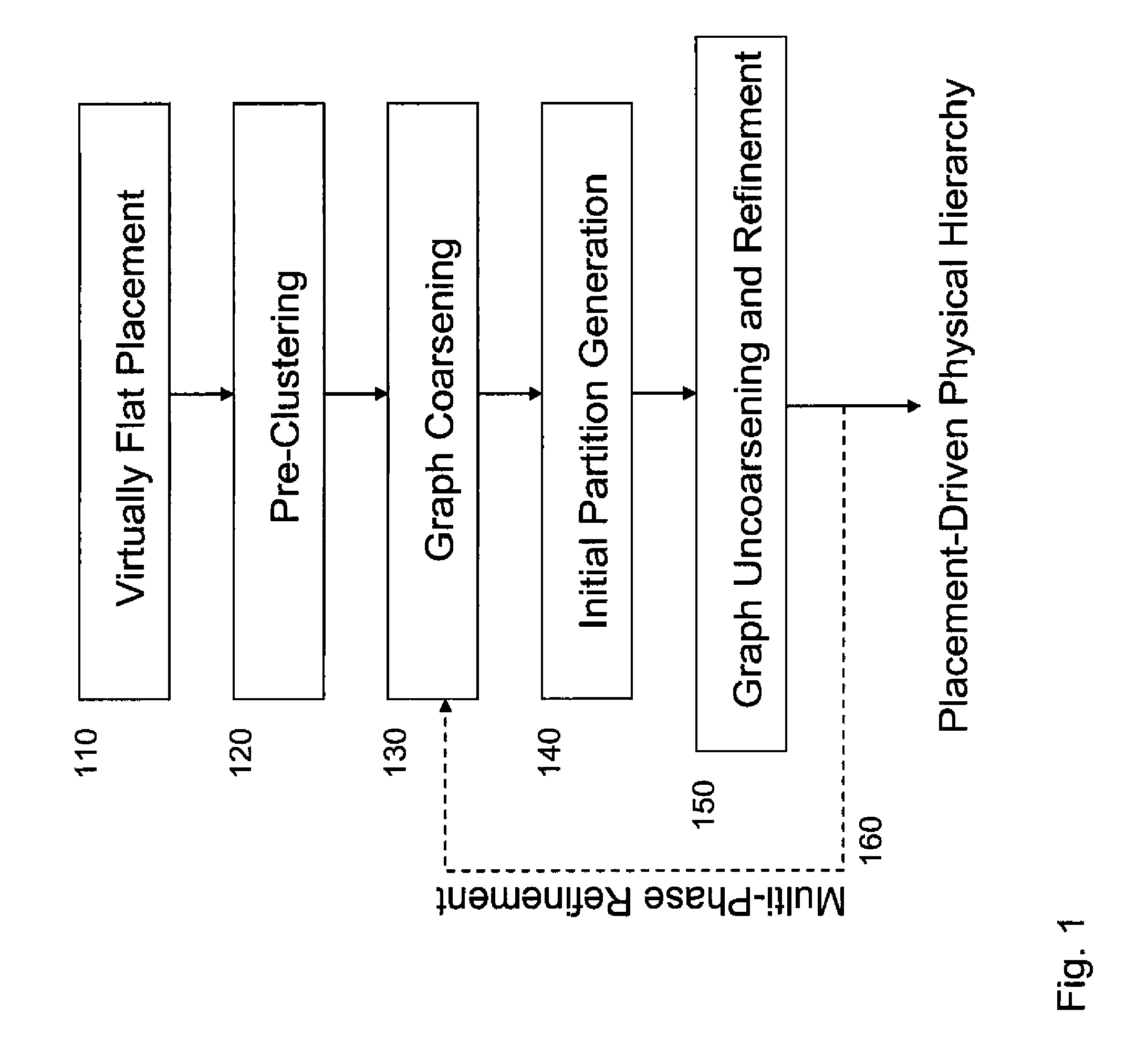
[0029] An embodiment of a method also includes pre-clustering. This includes processing the logical hierarchy in a top-down levelized order to locate and pre-cluster logical hierarchy cells with high placement affinity. An embodiment including graph coarsening comprises a method that performs a bottom-up clustering to reduce the size of the hypergraph, using the best choice clustering heuristic and a lazy update scheme for neighbor cost updates. A method also may include initial partition generation. For example, using a simplified n

Problems solved by technology

In an EDA physical design system, however, hierarchy introduces an extra level of complexity over flat design.
Leaf cells (standard cells and hard macros) are constrained to be placed within those artificial boundaries, possibly causing them to be moved from their optimal “flat” locations, increasing signal delay.
Signal routes between soft macros are similarly constrained to cross the soft macro boundaries only at pre-defined pin locations, which may also cause the routes to deviate from their optimal shortest paths.
Register-to-register paths that cross the boundaries must be budgeted such that the arrival times at the soft macro boundaries are fixed; incorrect budgets may lead to unsolvable interconnect optimization problems.
Increased signal delays, especially on large global signals between soft macros, can result from increased net lengths or increased routing congestion if floorplanning, pin assignment, or budgeting quality are poor.
Increases in net length and / or congestion also can result in increased signal integrity issues, for example, crosstalk delay and noise violations, I-R drop violations, and ringing due to inductance effects.
Increased wiring densities can lead to manufacturability problems due to higher defect rates and sub-wavelength lithography effects.
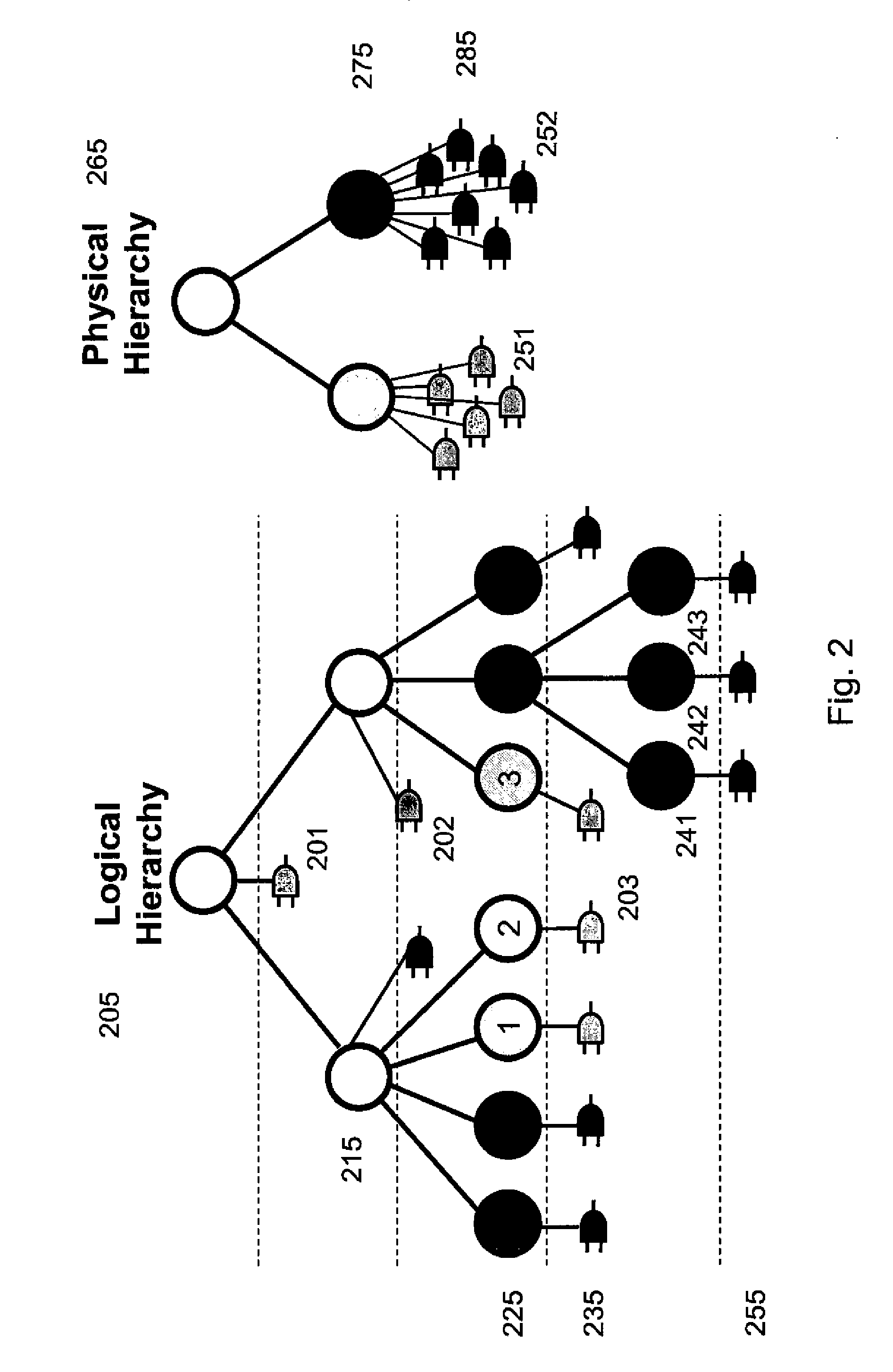
Second, the logical hierarchy is typically much deeper than the physical hierarchy.
Each additional level of physical hierarchy increases the complexity of the physical design process, and hence there are typically only one or two levels of physical hierarchy.
Third, blocks in the physical hierarchy are typically much larger than in the logical hierarchy.
The flat design capacity of modern EDA software tools is quite high, and the complexity of the physical design task increases with the number of blocks, so blocks in the physical hierarchy are typically made as large as possible.
Fourth, the logic design team often has little visibility into the physical design process or requirements.
However in the physical design this test logic must be distributed over the floorplan or, again, long wiring delays and congestion might occur.
However, it is different in a number of significant ways, and therefore requires a new approach and new algorithms.
Furthermore, it is not obvious a-priori what values of k may be optimal or even feasible.
While those figures of merit do correlate with physical parameters such as routing length and congestion, they are only indirect measures and not robust enough for an interconnect-centric flow.
Splitting a power domain into two partitions is not desirable because of the extra overhead required to distribute the power supply voltage to each partition, and to duplicate associated level shifting cells and / or power gating logic to each partition.
Splitting a clock domain into two partitions is not desirable because of the extra overhead required to route the clock network to each partition, or to duplicate the clock gating logic in each partition.

Method used


Image

  • Placement-Driven Physical-Hierarchy Generation
  • Placement-Driven Physical-Hierarchy Generation
  • Placement-Driven Physical-Hierarchy Generation

Examples


Embodiment Construction

[0039] Methods (and systems) for generation of a physical hierarchy based on placement are described. FIG. 1 is a flow chart illustrating a method for placement-driven physical-hierarchy generation in accordance with one embodiment. One of ordinary skill in the art will recognize that in alternative embodiments, some of the steps described in FIG. 1 are optional, and in addition, the steps can be performed in a different order. Examples of alternative embodiments follow the description of steps. Thus, FIG. 1 is merely an example of one embodiment.

A. Virtually-Flat Placement

[0040] Referring to FIG. 1, step 110 is the process of virtually-flat placement. By running a virtually-flat mixed-mode global placer on the entire design a first pass layout is accomplished. The phrase “virtually-flat” means placing all of the leaf cells in the design as if it were flat, even though it is not in fact actually flat. The intermediate levels of logical hierarchy are ignored. A global placer is re...


PUM


Abstract

A method and system for performing placement-driven physical hierarchy generation in the context of an integrated circuit layout generation system is provided. This generation optimizes the physical hierarchy to improve placement of the cells in the layout, and the associated interconnect routability and delay. A new pre-clustering phase is introduced to maintain as much of the input logical hierarchy as possible while maintaining physical hierarchy quality. And a new cost function is described which is based on measuring the mutual affinity of cells in a virtually-flat placement. The new cost function is used during the new pre-clustering phase, as well as the common clustering, partitioning, and declustering / refinement phases of physical hierarchy generation.

Description

CROSS REFERENCE TO RELATED APPLICATIONS [0001] This application claims a benefit, and priority, under 35 USC §119(e) to U.S. Provisional Patent Application No. 60 / 791,980, titled “Placement-Driven Physical-Hierarchy Generation”, filed Apr. 14, 2006, the contents of which are herein incorporated by reference.BACKGROUND [0002] 1. Field of the Art [0003] The disclosure herein relates generally to the field of integrated circuit design and more specifically to the automated layout design of semiconductor chips. [0004] 2. Description of the Related Art [0005] In an Electronic Design Automation (EDA) system for hierarchical integrated circuit (IC) design, the Physical Hierarchy Generation (PHG) step is responsible for partitioning the input netlist into a set of two or more hierarchical modules which can be referred to as soft macros. The PHG problem is the first step in any top-down hierarchical design planning system, and therefore, all proceeding steps depend of the quality of the PHG ...

Claims


Application Information

Patent Timeline
IPC IPC(8): G06F17/50G06F9/45
CPCG06F17/5072G06F30/392
Inventor RIEPE, MICHAEL A.BALASUNDARAM, NIRANJANAVERBEEK, MENNO EWOUTCAI, HONGCARPENTER, ROGERAVIDAN, JACOB
Owner MAGMA DESIGN AUTOMATION
Learn More