Rotor blade for wind energy plants

Inactive Publication Date: 2007-10-04
NORDEX ENERGY
View PDF3 Cites 29 Cited by
  • Summary
  • Abstract
  • Description
  • Claims
  • Application Information

AI Technical Summary

Benefits of technology

[0013]The present invention is based on the finding that in the conventional arrangement of the cross bores in equal distances from the hub-side rotor blade edge, the weakening of the rotor blade by the cross bores is increased because relatively little material between the bores remains when the cross bores are closely neighbouring each other. In addition, a material fracture along the straight line formed by the cross bores can be favoured in the conventional arrangement of the cross bores. Furthermore, when using the usual Triax material, in which parts of the fibre bundles run in an angle of about 45° to the longitudinal axis of the rotor blade, depending of the circumstances a big part of these angled fibres is severed by the closely neighbouring cross bores, which additionally decreases the stressability.
[0015]Through the arrangement of the cross bores according to the present invention it is achieved that at equal number of cross bores, the distances between two cross bores increase with respect to an arrangement on a straight line. Through this, a higher stability of the material remaining between two cross bores is achieved. The danger of a material fracture along the connection line between the cross bores is decreased. An additional advantage is that the blade flange can be made thinner in the region of the cross pins, through which the bending stress of the correspondingly shorter cross pins is decreased. As the case may be, the number of pins may also be increased. Altogether, the strength of the rotor blade fixture is improved.It is particularly advantageous that the realisation of a rotor blade according to the present invention is possible in a very simple way using conventional manufacturing techniques. No additional cost for the manufacture of the rotor blade or a changeover of an existing production worth to be mentioned is generated.
[0019]According to a further embodiment of the present invention, one longitudinal bore running transversely to the direction of the cross bore is provided for each cross bore, which leads from the cross bore to the hub-side rotor blade edge and which accommodates the tensioning elements. Thus, in this case the tensioning elements are in the interior of the rotor blade shell. Alternatively, it is also possible to guide the tensioning elements outside the rotor blade shell, by which an additional weakening of the rotor blade shell through the longitudinal bores can be avoided. However, when guiding the tensioning element inside a longitudinal bore in the rotor blade shell, an advantageous symmetrical connection to the cross pin can be realised with one single tensioning element.
[0020]In a further embodiment of the present invention, the cross bores are realised as pocket bores. I.e., the cross bores are not realised as through bores, which run through the entire wall of the rotor blade, but they serve for the accommodation of shorter cross pins. Through this, the weakening of the rotor blade by each individual cross bore can be avoided.
[0021]According to a further preferred embodiment of the present invention, the wall of the rotor blade is reinforced in the region of the cross bores. For the purpose of reinforcement, the thickness of the material in this region may be enhanced, by additional fibre layers for instance, or additional reinforcement elements can be applied to the wall of the rotor blade or be incorporated into it.

Problems solved by technology

Furthermore, when using the usual Triax material, in which parts of the fibre bundles run in an angle of about 45° to the longitudinal axis of the rotor blade, depending of the circumstances a big part of these angled fibres is severed by the closely neighbouring cross bores, which additionally decreases the stressability.

Method used


Image

  • Rotor blade for wind energy plants
  • Rotor blade for wind energy plants
  • Rotor blade for wind energy plants

Examples


Embodiment Construction

[0026]While this invention may be embodied in many different forms, there are described in detail herein a specific preferred embodiment of the invention. This description is an exemplification of the principles of the invention and is not intended to limit the invention to the particular embodiment illustrated

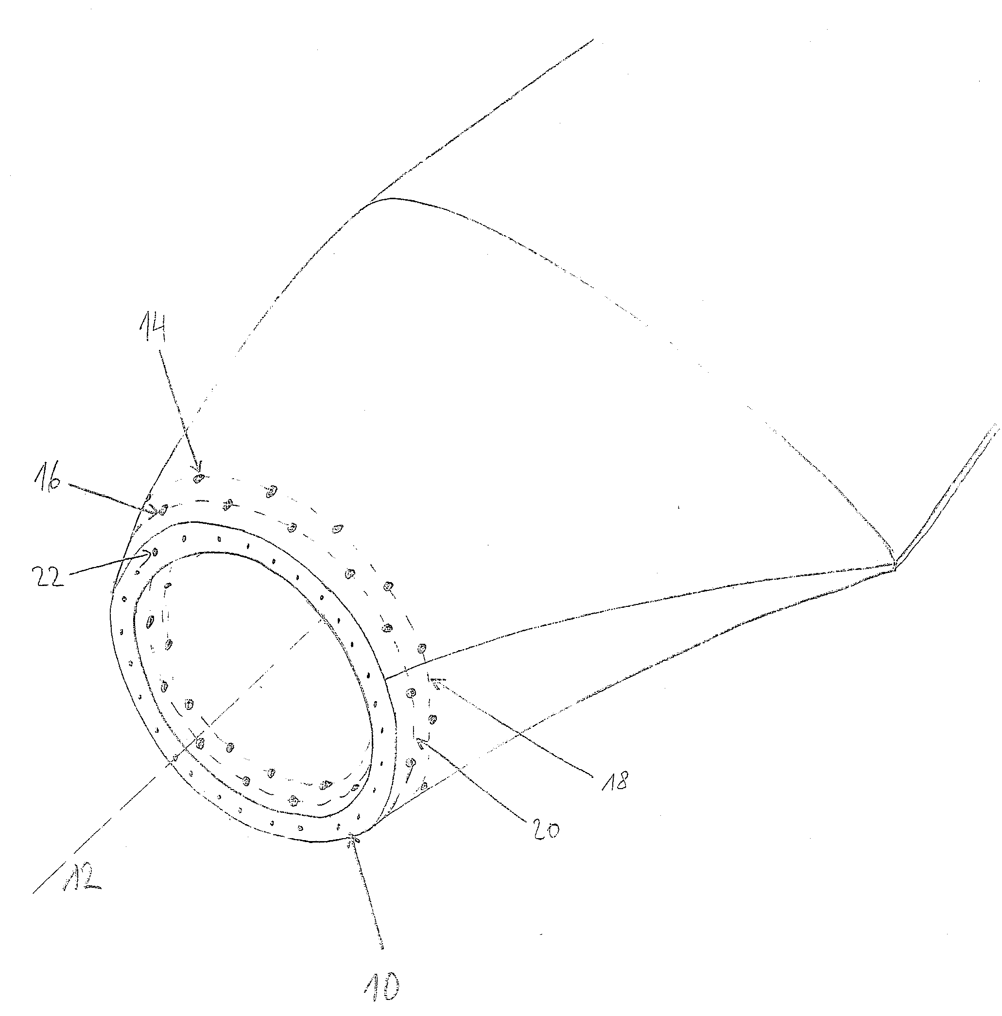
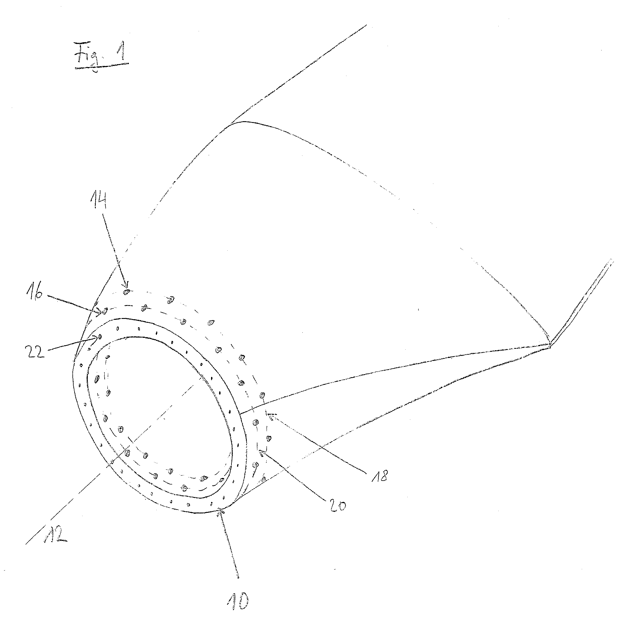
[0027]The rotor blade, the blade base of which is outlined in FIG. 1, is made up of two half-shells from fibre reinforced plastic material in a per se known manner. On the hub-side end of the rotor blade, there is the hub-side rotor blade edge 10, which is formed by an approximately circular annular plane. The width of the ring corresponds to the material thickness of the rotor blade shells in this region. The longitudinal axis of the rotor blade is indicated at 12. The hub-side rotor blade edge 10 is aligned essentially vertical to the longitudinal axis 12.

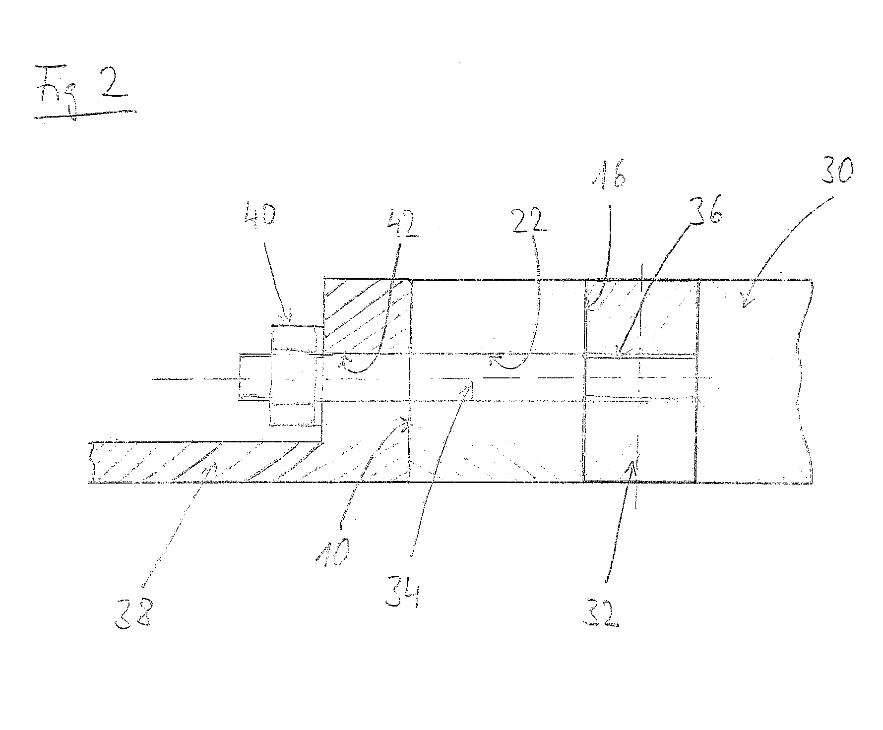
[0028]The rotor blade is provided with a multiplicity of cross bores 14, 16. The cross bores 14, 16 are aligned transvers...


PUM


Abstract

A rotor blade for wind energy plants with a multiplicity of cross bores running transversely to the longitudinal axis of the rotor blade in the region of the blade base, which are provided for the accommodation of cross pins, wherein for fastening the rotor blade on a rotor blade fixture, tensioning elements act upon the cross pins wherein at least one of the cross bores has a distance from the hub-side rotor blade edge which is different from the distance of a further cross bore from the rotor blade edge.

Description

CROSS-REFERENCE TO RELATED APPLICATIONS[0001]Not applicable.STATEMENT REGARDING FEDERALLY SPONSORED RESEARCH[0002]Not applicable.BACKGROUND OF THE INVENTION[0003]The present invention is related to a rotor blade for wind energy plants with a multiplicity of cross bores, running transversely to the longitudinal axis of the rotor blade in the region of the blade base, which are provided for receiving cross pins, wherein for fastening the rotor blade on a rotor blade fixture, tensioning elements act upon the cross pins.[0004]Such fastening solutions for rotor blades with cross pins and tensioning elements are commonly known. In modern wind energy plants, high mechanical loads occur in the connection region between hub and rotor blades. These loads increase significantly with wind energy plants becoming larger and larger. In connection with the intended weight saving construction, this necessitates highest demands on the construction of the parts for mounting the rotor blade. Accordingl...

Claims


Application Information

Patent Timeline
IPC IPC(8): B64C11/04
CPCY02E10/721F03D1/0658Y02E10/72
Inventor BIRKEMEYER, JOCHENROCHHOLZ, HERMANN
Owner NORDEX ENERGY
Why Eureka
Try Eureka