
Pocket assembly for placing a flat dowel between cast in place concrete slabs

a technology of cast in place concrete and dowel, which is applied in the direction of paving details, roads, constructions, etc., can solve the problems of cement intruding into the dowel and the spacer, and achieve the effect of avoiding cement intrusion

Inactive Publication Date: 2007-10-04
MMI PRODS
View PDF19 Cites 33 Cited by
  • Summary
  • Abstract
  • Description
  • Claims
  • Application Information

AI Technical Summary

Benefits of technology

[0017]A further object of the invention is to provide such an assembly wherein seals are provided to prevent the intrusion of fluid concrete into the pocket forming member during the formation of a concrete slab.

Problems solved by technology

A disadvantage of the prior art spacers and sheaths is that either the dowel, or some type of a mounting plate is disposed within and extends from the dowel or sheath during its placement within the slab being formed.
This requires that the form be configured to accommodate the plate or dowel and also risks that cement may intrude around the dowel and the spacer, during the formation of the concrete slab.

Method used


Image

  • Pocket assembly for placing a flat dowel between cast in place concrete slabs
  • Pocket assembly for placing a flat dowel between cast in place concrete slabs
  • Pocket assembly for placing a flat dowel between cast in place concrete slabs

Examples


second embodiment

DESCRIPTION OF THE SECOND EMBODIMENT

[0059]The pocket forming member of this embodiment is illustrated in FIG. 8 and identified, in its entirety, by the reference letter P2. The member P2 is injection molded from the same type of polymer described with reference to the pocket forming member P1 of the first embodiment. It differs from the first embodiment primarily in that it does not have longitudinally extending ribs within the pocket and in the structure of the stop members and fastening structure. It also differs in that a door 36 is provided to close the opening in the pocket forming member P2.

[0060]The pocket forming member P2 is similar to the member P1 in that it comprises upper and lower sections 40 and 42, respectively, hingedly secured together by an integrally formed hinge 44. The upper section is formed with side walls 48 and the lower section is formed with side walls 50. The fastener member of the second embodiment comprises flanges 52 and 54 which provide a collar exte...

third embodiment

DESCRIPTION OF THE THIRD EMBODIMENT

[0068]The pocket forming member of this embodiment is identified, in its entirety, by the reference letter P3. The member P3 is injected molded from the same type of polymer described with reference to the pocket forming members P1 and P2 of the first and second embodiments. It comprises an upper section 100 and a lower section 102 disposed for movement toward one another, as depicted in FIG. 21A, and is similar to the second embodiment in that it has a flanged open end (see FIG. 21C). The flanged open end is provided by a first flange 104 on the upper section 100 and a second flange 106 on the lower section 102, These flanges are similar to the flanges 52, 54 and are formed with open ended slots 105, 107.

[0069]The sections 100 and 102 differ from the sections 40 and 42 of the second embodiment in that the upper section 100 is of a shallower depth than the upper section 40 and in that the sections are not hingedly joined. Rather, they are provided ...


PUM


Abstract

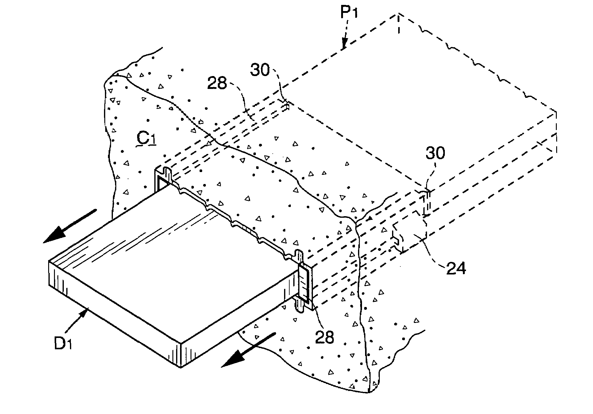
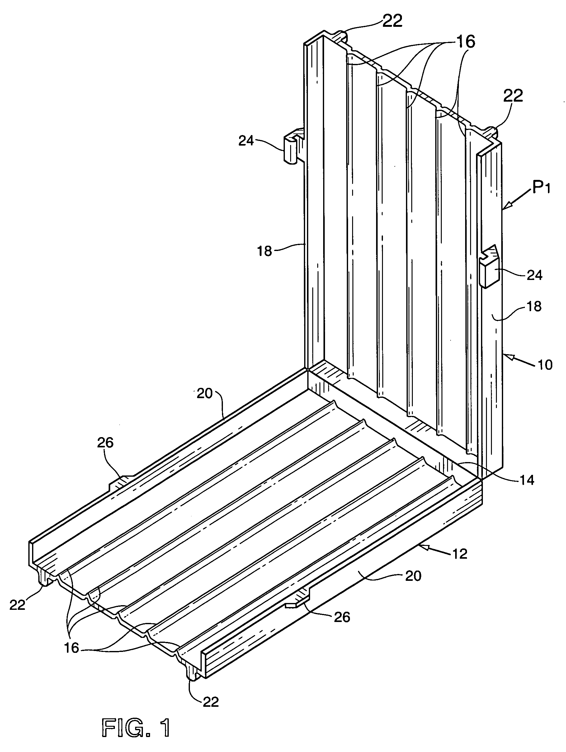
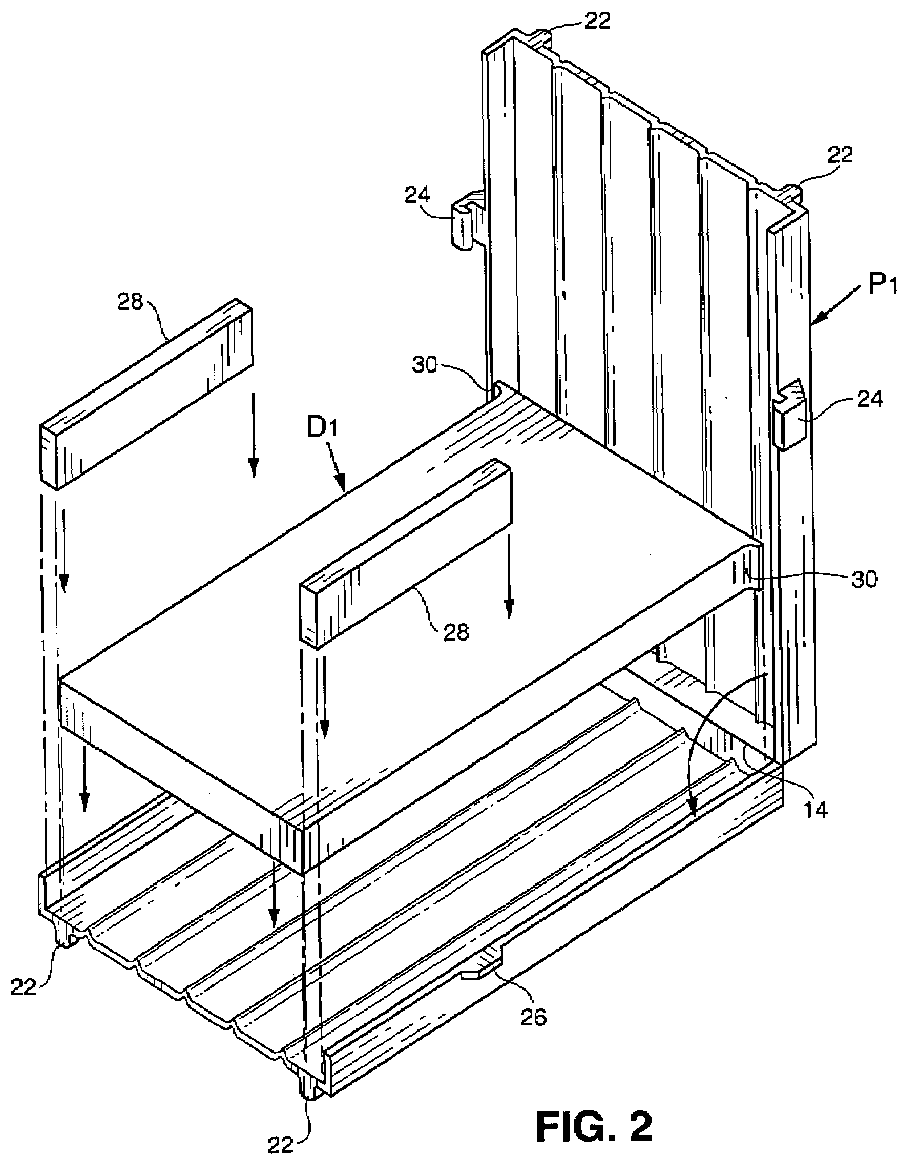
An assembly for use in the formation of adjacent concrete slabs to provide a flat rectangular dowel engaged between the slabs. The assembly comprises a pocket which is cast in place in the edge portion of the first slab to be formed, with the dowel fully confined within the pocket. After the formation of the first slab, the dowel is partially withdraw from the pocket and the second slab is formed in place against the first slab, with the dowel in spanning relationship to the respective slabs. In the preferred embodiments, the pocket comprises a monolithic plastic box having complimental generally rigid upper and lower sections movable between a closed condition defining the pocket therebetween and an open condition exposing the pocket interiorly. One edge of the pocket is formed with an opening through which the dowel passes as it moves between the fully confined and the partially withdrawn positions. In certain embodiments, a sealing element or door is provided to close the opening during the formation of the first slab. Seal elements are also provided to seal the pocket against the intrusion of concrete during the formation-of the second slab.

Description

RELATED APPLICATION[0001]This application is based upon and claims the benefit of Provisional Application 60 / 787,125, filed Mar. 29, 2006.BACKGROUND OF THE INVENTION[0002]The present invention relates to an assembly for use in the formation of adjacent concrete slabs to provide an embedded flat planar dowel to maintain the slabs in generally horizontal alignment, while permitting limited lateral movement of the slabs relative to one another. In its more specific aspects, the invention is concerned with such an assembly which provides a pocket cast in place within the first slab to be formed and a dowel within the pocket which may be partially withdrawn for embedment within the second slab to be formed.[0003]The provision of dowels to transfer loads between adjacent cast in place concrete slabs is well known. Generally these dowels are a conventional cylindrical configuration. It is also known to provide dowels for this purpose which are of a flat diamond-shape, as may be seen from U...

Claims


Application Information

Patent Timeline
Patent Type & Authority Applications(United States)
IPC IPC(8): E01C11/14
CPCE01C11/14
Inventor FRANCIES, SIDNEY E.KELLY, DAVID L.
Owner MMI PRODS
Learn More