
Communication link for rotating turret

a technology of communication link and rotating turret, which is applied in the direction of data switching network, instruments, manufacturing tools, etc., can solve the problems of limited life components, twisting of conventional wire connections, and very data intensive video signals

Inactive Publication Date: 2007-10-04
EL OP ELECTRO OPTICS INDS
View PDF9 Cites 13 Cited by
  • Summary
  • Abstract
  • Description
  • Claims
  • Application Information

AI Technical Summary

Benefits of technology

[0041] Preferably, said first communication link is a control link for passing control signals, and wherein there is provided a second communication

Problems solved by technology

The resulting video signals are very data intensive and need to be transferred to a computer or the like for processing.
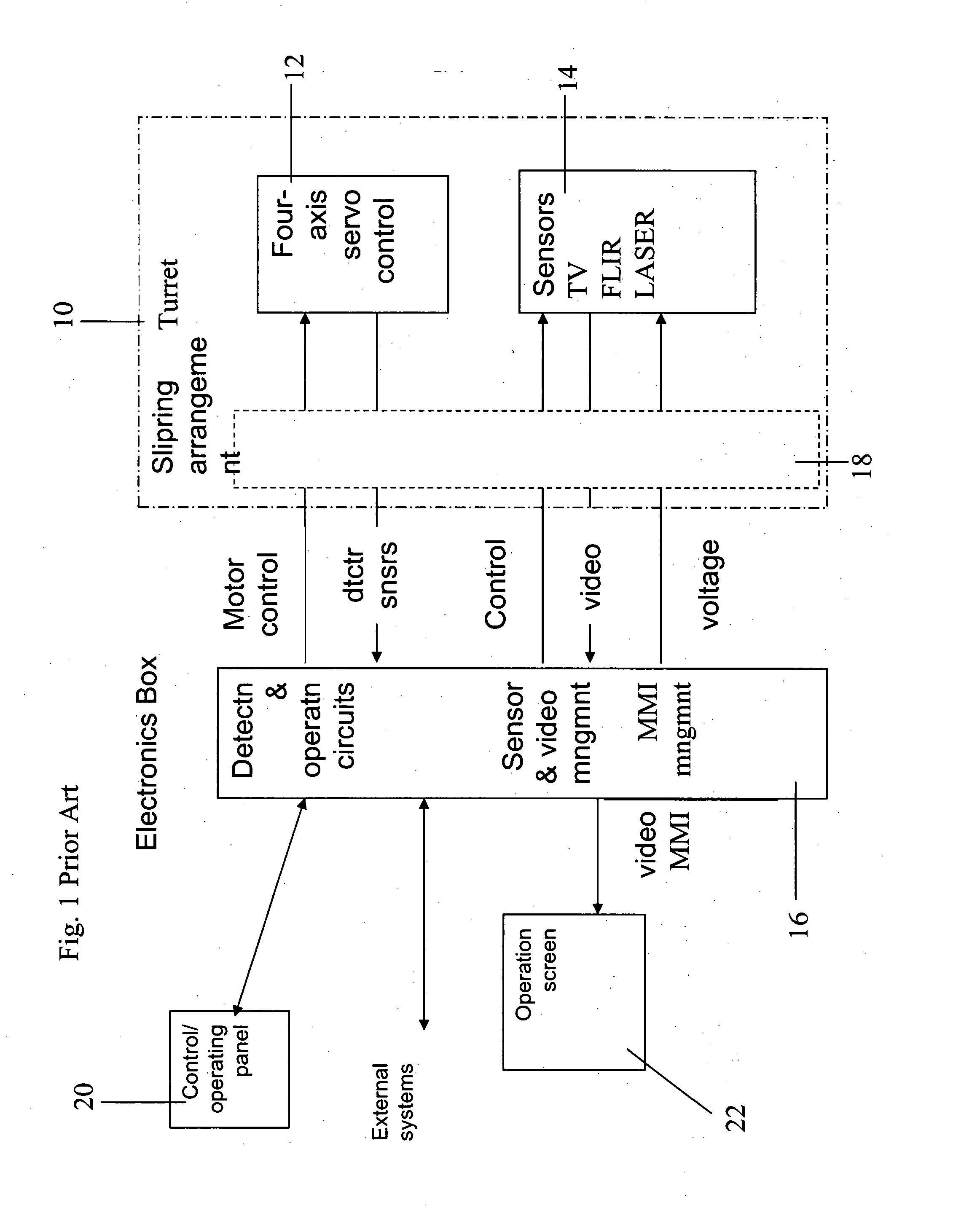
The data connections for the various devices in the turret need to remain functional despite free rotation of the turret, and yet rotation of the turret can lead to twisting of conventional wire connections.
Unfortunately slip rings are limited life components, which are often the cause of system failure and require regular maintenance.
Furthermore there are only a limited number of slip rings that can be inserted into a single turret system and so the number of observation devices that can be inserted into the turret is limited.
The capacity for slip rings thus limits the scope for upgrading of the turret.
The number of slip rings is limited by physical space and also by weight.
Slip rings are relatively heavy and expensive components and even a very small number of devices in the turret may require tens of electrical connections.
It will be appreciated that weight is an important issue when the turret is intended to be mounted on an aircraft, and especially if the turret is to be mounted on a drone, which may be quite small.
As the devices are all incompatible, each device has its own connection or connections to the outside world.
The turret slipring arrangement has only limited capacity for additional sliprings and therefore provides a limit to the number of devices that can be inserted into the turret.
Furthermore the need to include a new slipring for a new device makes installation a complex operation.
The limiting factor is the capacity for adding more rotatable connections and slip rings, and not the physical space in the turret.

Method used


Image

  • Communication link for rotating turret
  • Communication link for rotating turret
  • Communication link for rotating turret

Examples


Embodiment Construction

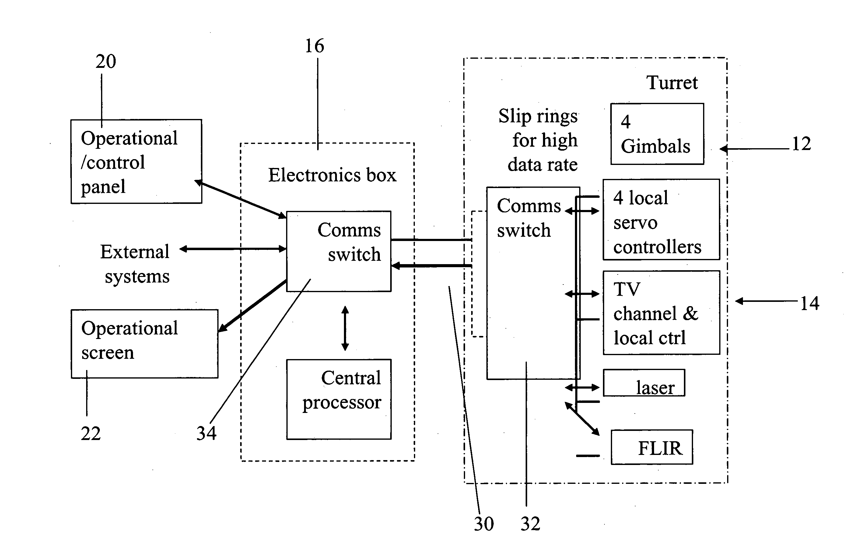
[0054] The present embodiments comprise an observation turret having a communication switch located within the turret and connected to the various observation and servo devices. The switch in turn is connected to an aggregated data link, typically a wideband digital data link, and typically having a high data rate, which connects between the turret itself and the external world. The switch permits all of the devices in the turret to use separate channels on the same data link for communication, and the result is a more robust turret system with a much reduced need for connections. The wideband link may be a wireless link such as radio or IR or microwave or ultrasound or an optical link or the like. Alternatively it may be a wired link or a link using waveguides. The number of slip rings is greatly reduced and additional devices can be added at will as long as there is space in the turret, and capacity at the switch and over the link. No additional rotating connections are needed whe...


PUM

PropertyMeasurementUnit
Poweraaaaaaaaaa
Flexibilityaaaaaaaaaa

Abstract

Communication system for a rotating turret having a plurality of electronic components, comprises: a first aggregated communication link connecting between the turret and external electronics, and a first internal communication switch located within the turret for connecting each of the plurality of electronic devices to a channel of the aggregated communication link.

Description

RELATED APPLICATIONS [0001] This Application is a continuation-in-part of PCT Patent Application No. PCT / IL2005 / 001009, filed on Sep. 21, 2005 which claims the benefit of Israel Patent Application No. 164226, filed on Sep. 22, 2004, the contents of which are hereby incorporated by reference.FIELD AND BACKGROUND OF THE INVENTION [0002] The present invention relates to a communication link for a rotating turret and, more particularly, but not exclusively to a communication link for an observation turret designed to house observation equipment and to be fully and freely rotatable in order to track targets even if the turret is mounted in a rapidly moving vehicle and / or the target is moving rapidly and freely. [0003] Observation turrets typically house one or more observation devices such as video cameras, FLIR cameras, LASER devices, and the like. The resulting video signals are very data intensive and need to be transferred to a computer or the like for processing. The current archite...

Claims


Application Information

Patent Timeline
IPC IPC(8): H04L12/50F41H5/20B23K11/24G08C15/00H04N
CPCG08C15/00G08C17/00G08C19/00
Inventor PORAT, ZVIBESSERGLIK, DVIR
Owner EL OP ELECTRO OPTICS INDS
Learn More