
Generation of trace elements within a data processing apparatus

a data processing apparatus and trace element technology, applied in the field of trace element generation, can solve the problems of limiting the rate at which information can be stored in the trace buffer, and increasing the power and complexity of the processor core, so as to save bandwidth and/or storage space, and the effect of saving storage costs

Active Publication Date: 2007-09-27
ARM LTD
View PDF14 Cites 18 Cited by
  • Summary
  • Abstract
  • Description
  • Claims
  • Application Information

AI Technical Summary

Benefits of technology

[0014] In accordance with the present invention the trace logic is arranged, when generating a trace element to represent a data element, and if at least a part of the data element is derivable from a control value stored in a storage element accessible to the trace logic, to omit that part of the associated data element indication from the corresponding trace element, instead including a reference to that storage element. This enables a significant reduction in the amount of trace data required to be produced, in situations where the data element can later be reconstructed with reference to the control value.
[0017] Through use of the present invention, it has been found that the volume of trace elements that need to be generated to track the activity of the device under test can be significantly reduced whilst still enabling a similar amount of information about the activities of the device to be deduced by a trace analysing tool. All that is required is for the trace analysing tool to maintain a copy of the control values in the storage elements referenced by the trace generating logic which can then be used when reconstructing the omitted information.
[0020] The storage elements may be provided specifically for the purpose of being referenced by the trace generation logic. However in one embodiment, the trace logic further comprises control logic operable to determine which of said data elements are to be represented by said stream of trace elements, the control logic being operable to reference the control value in said at least one storage element when performing said determination. Hence, a user is able to define, by storing appropriate control values in the available storage elements, which received data elements are of interest and should therefore be represented in the generated stream of trace elements. This may for example be achieved by specifying particular values of data elements of interest in the storage elements, or by specifying ranges of values. In this embodiment, these same storage elements are then referenced by the trace generation logic when deciding whether at least a part of a data element to be traced can be derived from a control value stored therein. Moreover, since such storage elements for steering the operation of the trace generation logic, under the control of associated control logic, are a typical feature of a block of trace logic, the references made to these storage elements by the trace generation logic are possible without the need to provide expensive additional storage space on-chip explicitly for storing such references.
[0022] In one embodiment, said trace logic is operable to output said stream of trace elements for analysis by a trace analysing tool which has knowledge of the control value stored in each storage element. Thus, the trace analysing tool may reconstruct an indication of the data element traced, by identifying the storage element indication in the trace element and referencing the control value known to be stored in that storage element. In this way, the trace analysing tool has access to a greater quantity of information about the device under test than it is necessary for the trace generation logic to output in the stream of trace elements, saving bandwidth and / or storage space in an environment where both are precious.

Problems solved by technology

However, with the general move towards more deeply embedded processor cores, it becomes more difficult to track the activities of the processor core or other on-chip devices via externally accessible pins.
It has been found that the bandwidth of the dedicated data bus limits the rate at which information can be stored in the trace buffer.
As devices such as processor cores increase in power and complexity, it is clear that the amount of information required to track the activities of such devices will increase, and accordingly there will potentially be a very large volume of trace elements that need to be traced.
However, there is a problem that there is finite bus bandwidth over which the trace elements can be output by the trace logic, and any trace buffer used to buffer such trace elements will have a finite size.
Whilst such an approach provides some benefits in reducing the volume of trace elements produced, it requires the maintenance of a table within the trace logic, and can only start to reduce the amount of trace once the table has been populated to provide a history of architectural state that has already been provided by previous trace elements of the trace stream.

Method used


Image

  • Generation of trace elements within a data processing apparatus
  • Generation of trace elements within a data processing apparatus
  • Generation of trace elements within a data processing apparatus

Examples


Embodiment Construction

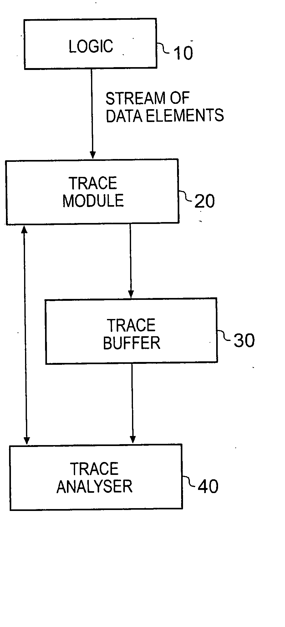
[0042]FIG. 1 schematically illustrates a data processing system providing logic 10, a trace module 20, a trace buffer 30 and a trace analyser 40. Whilst FIG. 1 illustrates a data processing system providing a trace buffer 30, in alternative embodiments the trace module 20 may pass its output straight to the trace analyser 40, without going via a trace buffer.

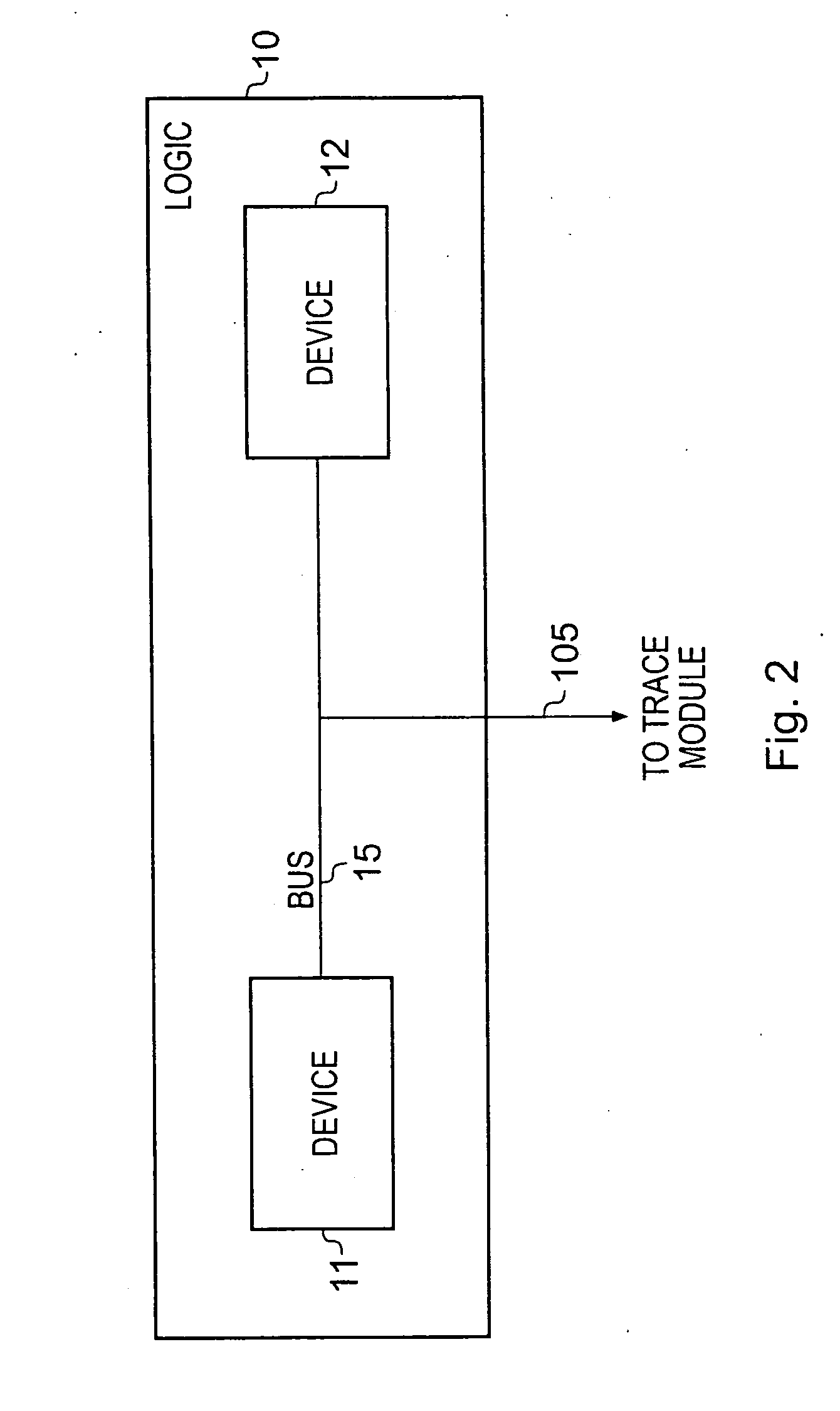
[0043] The logic 10 producing the stream of data elements received by the trace module 20 can take a variety of forms, and may for example be a processor core, a Direct Memory Access (DMA) engine, a data engine / accelerator, etc. Alternatively, the logic 10 may consist of a plurality of devices coupled by a bus, and the data elements may be monitored by the trace module 20 as they pass over the bus.

[0044] The trace analyser 40, which may in one embodiment be formed by a general purpose computer running appropriate software, is coupled to the trace module 20 and the trace buffer 30. The trace module 20, typically embodied on-chi...


PUM


Abstract

A data processing apparatus and method for generating trace elements is provided. The data processing apparatus comprises logic producing a series of data elements, indicative of the operation or state of all or part of the logic. Trace logic is provided for receiving indications of these data elements, and for generating from the indications a stream of trace elements. When for a given data element, at least part of the data element is derivable from a reference to a control value stored in a storage element, the trace logic is operable, dependent on that data element, to omit that part of the associated data element indication from the corresponding trace element generated in respect of the data element, instead including a reference to the corresponding storage element. A trace analysing apparatus can then be used to reconstruct such omitted information based on a copy of the relevant storage element.

Description

BACKGROUND OF THE INVENTION [0001] 1. Field of the Invention [0002] The present invention relates to the generation of trace elements representative of at least some data elements produced by logic within a data processing apparatus. [0003] 2. Description of the Prior Art [0004] Tracing the activity of a data processing system whereby a stream of trace elements is generated including data representing the step-by-step activity within the system is a highly useful tool in system development. However, with the general move towards more deeply embedded processor cores, it becomes more difficult to track the activities of the processor core or other on-chip devices via externally accessible pins. Accordingly, as well as off-chip tracing mechanisms for capturing and analyzing trace data, increased amounts of tracing functionality are being placed on-chip. An example of such on-chip tracing mechanisms is the Embedded Trace Macrocell (ETM) provided by ARM Limited, Cambridge, England, in as...

Claims


Application Information

Patent Timeline
IPC IPC(8): G06F11/00
CPCG06F11/3636
Inventor WOODHOUSE, SHELDON JAMES
Owner ARM LTD
Learn More