
System and method for servicing storage devices in a bladed storage subsystem

a storage subsystem and blade technology, applied in the field of storage systems, can solve the problems of increased write penalty of schemes such as 3-fault-tolerant schemes, failure to remove and replace failed drives, and low storage efficiency of schemes such as raid 51

Inactive Publication Date: 2007-09-27
GLOBALFOUNDRIES INC
View PDF6 Cites 15 Cited by
  • Summary
  • Abstract
  • Description
  • Claims
  • Application Information

AI Technical Summary

Benefits of technology

[0009] The present invention satisfies this need, and presents a system, a service, a computer program product, and an associated method (collectively referred to herein as “the system” or “the present system”) for servicing storage devices in a bladed storage subsystem. A tray of the bladed storage subsystem comprises one or more functional storage devices.
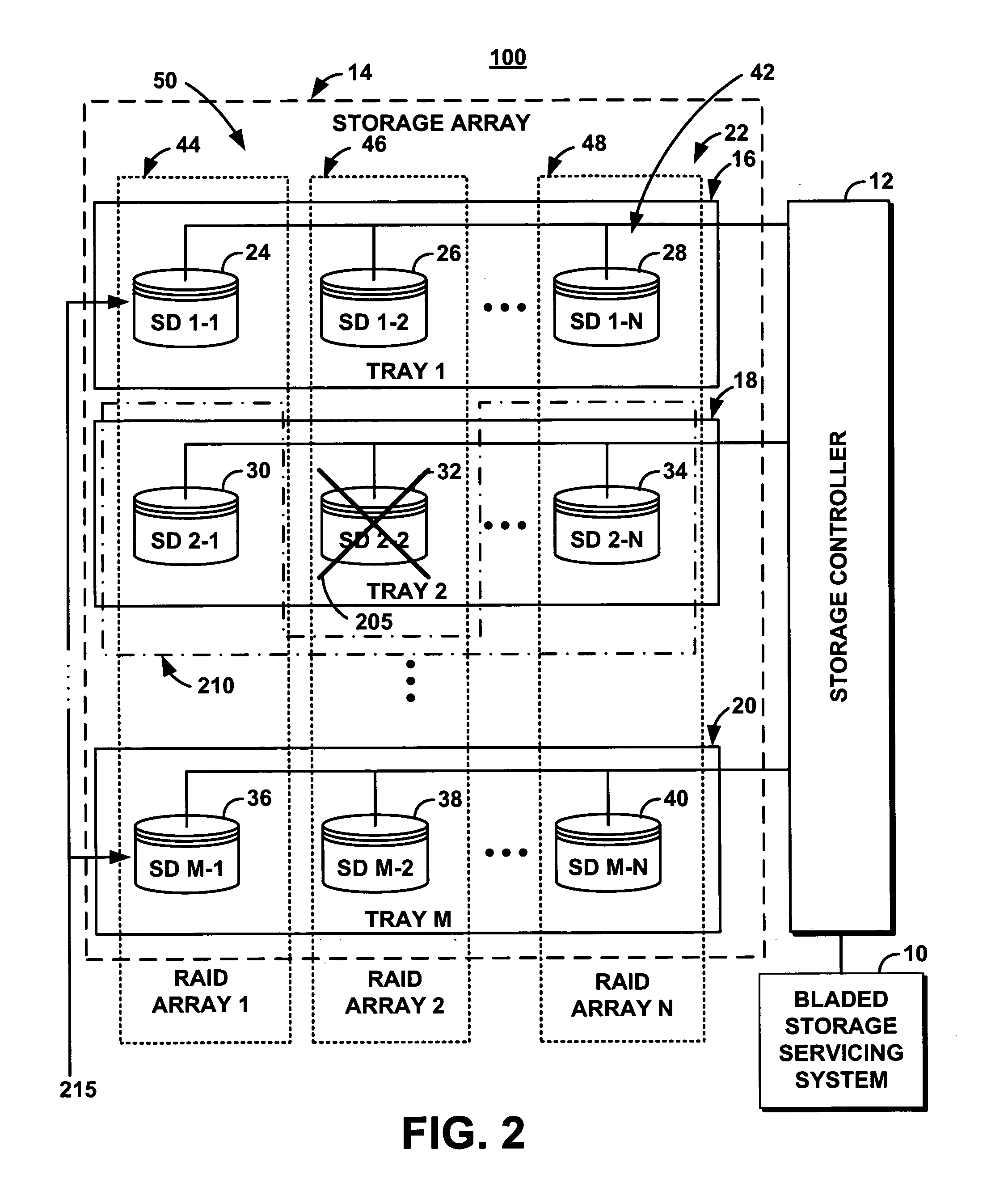
[0010] The present system introduces the concept of temporary removal of functional storage devices. Upon detection of the removal of the tray from the bladed storage subsystem, the present system designates the functional devices on the removed tray as temporarily removed. Subsequently, it logs all writes to these functional storage devices so that the functional storage devices can be returned to consistency when replaced in the bladed storage subsystem. The present system manages reads to the removed functional storage devices through reconstruction from some or all of a plurality of storage devices in the bladed storage subsystem that are not removed from the bladed storage subsystem. Upon reinsertion of the tray in the bladed storage subsystem, the present system resynchronizes the functional storage devices to ensure data consistency.
[0011] The present system verifies the identities of the functional storage devices on reinsertion into the bladed storage subsystem. The bladed storage subsystem comprises a RAID layout. The RAID layout comprises no more storage devices per tray than allowed by the fault tolerance of the RAID scheme.

Problems solved by technology

A bladed storage subsystem comprising more than one disk drive per tray presents a problem in removal and replacement of failed drives.
However, in this solution, some schemes (such as RAID 51) do not have high storage efficiency.
Other schemes (such as 3-fault-tolerant schemes) exhibit an increased write penalty.
Furthermore, some RAID schemes (such as RAID 6) may not be able to support configurations with three or more drives per tray.
However, relocating all data to a spare tray requires that the service action cannot be performed until the lengthy relocation operation is completed.
Furthermore, spare trays may not be available in all configurations.
The need for such a solution has heretofore remained unsatisfied.

Method used


Image

  • System and method for servicing storage devices in a bladed storage subsystem
  • System and method for servicing storage devices in a bladed storage subsystem
  • System and method for servicing storage devices in a bladed storage subsystem

Examples


Embodiment Construction

[0017]FIG. 1 illustrates an exemplary high-level architecture of a storage system 100 comprising a system and an associated method (the “bladed storage servicing system 10” or the “system 10”). System 10 includes a software programming code or computer program product that is typically embedded within, or installed on a computer. Alternatively, this program can be saved on a suitable storage medium such as a diskette, a CD, a hard drive, or like devices.

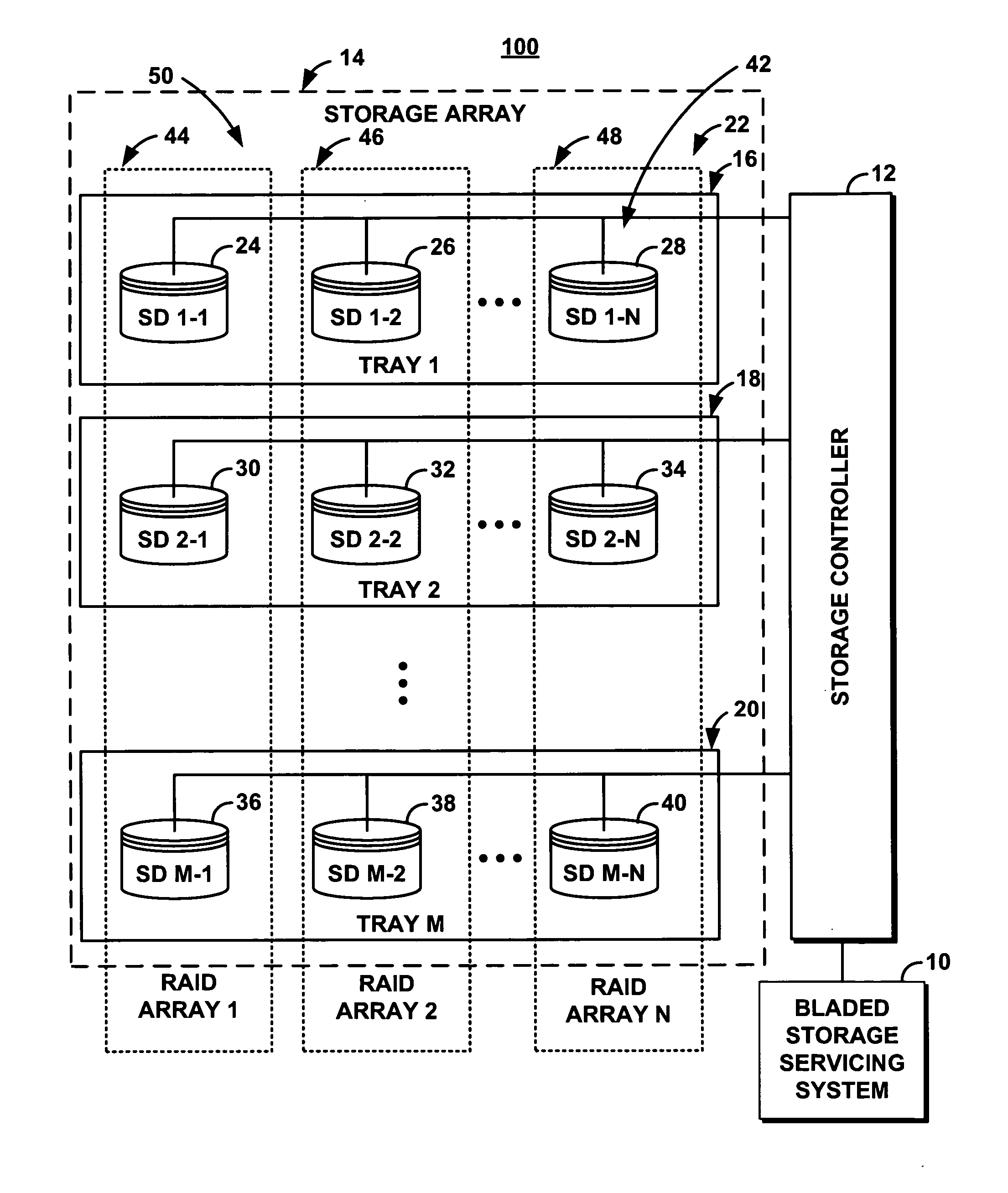
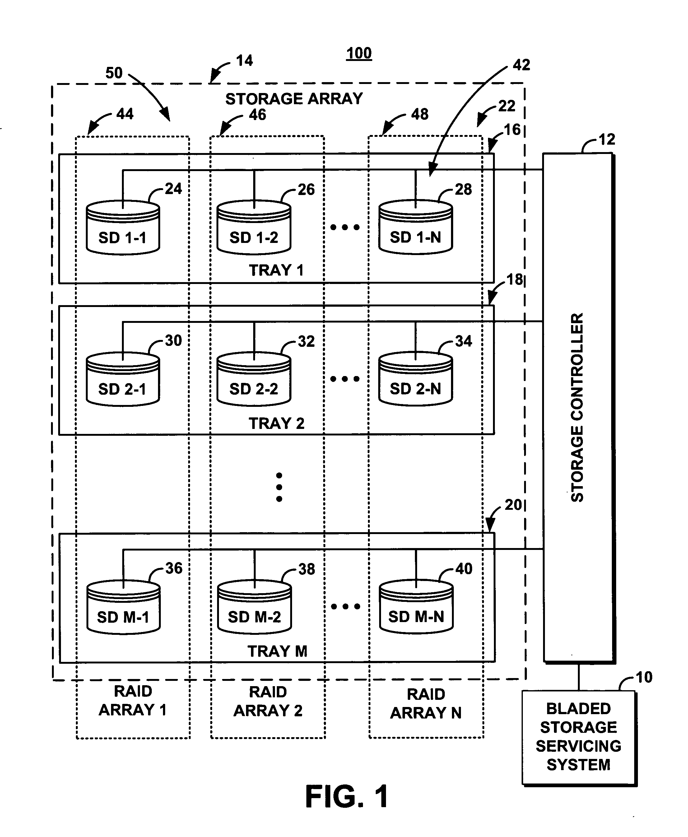
[0018] The storage system 100 comprises a storage controller 12. The storage controller 12 controls storage devices in a storage array 14. The storage array 14 comprises a tray 1, 16, a tray 2, 18, through a tray M, 20 (collectively referenced as trays 22). Tray 1, 16, comprises storage devices such as storage device 1-1 (SD 1-1), 24, storage device 1-2 (SD 1-2), 26, through storage device 1-N (SD 1-N), 28. Tray 2, 18, comprises storage devices such as storage device 2-1 (SD 2-1), 30, storage device 2-2 (SD 2-2), 32, through storage...


PUM


Abstract

A bladed storage servicing system comprising a RAID layout facilitates the removal of one or more functional storage devices in a tray of the bladed storage subsystem in order to service a failed storage device. Upon removal of the tray from the bladed storage subsystem, the system designates the functional storage devices on the tray as temporarily removed. The system logs writes to the removed functional storage devices so that the functional storage devices can be returned to consistency when replaced in the bladed storage subsystem. The system manages reads to the removed functional storage devices through reconstruction from active storage devices in the bladed storage subsystem. Upon reinsertion of the tray in the bladed storage subsystem, the system verifies the identities of the functional storage devices and resynchronizes the functional storage devices to ensure data consistency.

Description

FIELD OF THE INVENTION [0001] The present invention generally relates to storage systems, and in particular to a storage array configured for easy service of storage devices or replacement of failed storage devices in bladed storage subsystems. BACKGROUND OF THE INVENTION [0002] Blade-based computing systems are increasingly becoming popular in data center deployments. Blade-based systems provide efficient utilization of floor space, ease of installation and management, improved RAS (Reliability Availability and Serviceability), reduction in cabling requirements, integrated networking, and integrated storage. [0003] In one approach to blade-based computing systems, storage controllers are packaged into blade form-factors and integrated into the same enclosure as server blades. Storage devices such as disk drives are housed in a separate enclosure. To further improve packaging densities and to realize a complete system in a frame (i.e., a datacenter in a box) methods are being invest...

Claims


Application Information

Patent Timeline
Patent Type & Authority Applications(United States)
IPC IPC(8): G06F11/00
CPCG06F11/1088
Inventor HAFNER, JAMES LEESURUGUCCHI, KRISHNAKUMAR
Owner GLOBALFOUNDRIES INC
Learn More