
Combination vertical and lateral flow immunoassay device

Inactive Publication Date: 2007-09-27
BECTON DICKINSON & CO
View PDF28 Cites 70 Cited by
  • Summary
  • Abstract
  • Description
  • Claims
  • Application Information

AI Technical Summary

Benefits of technology

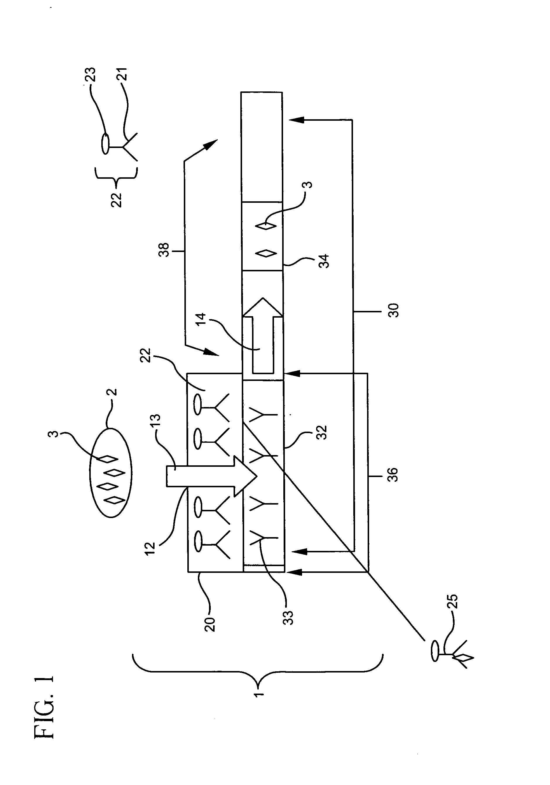
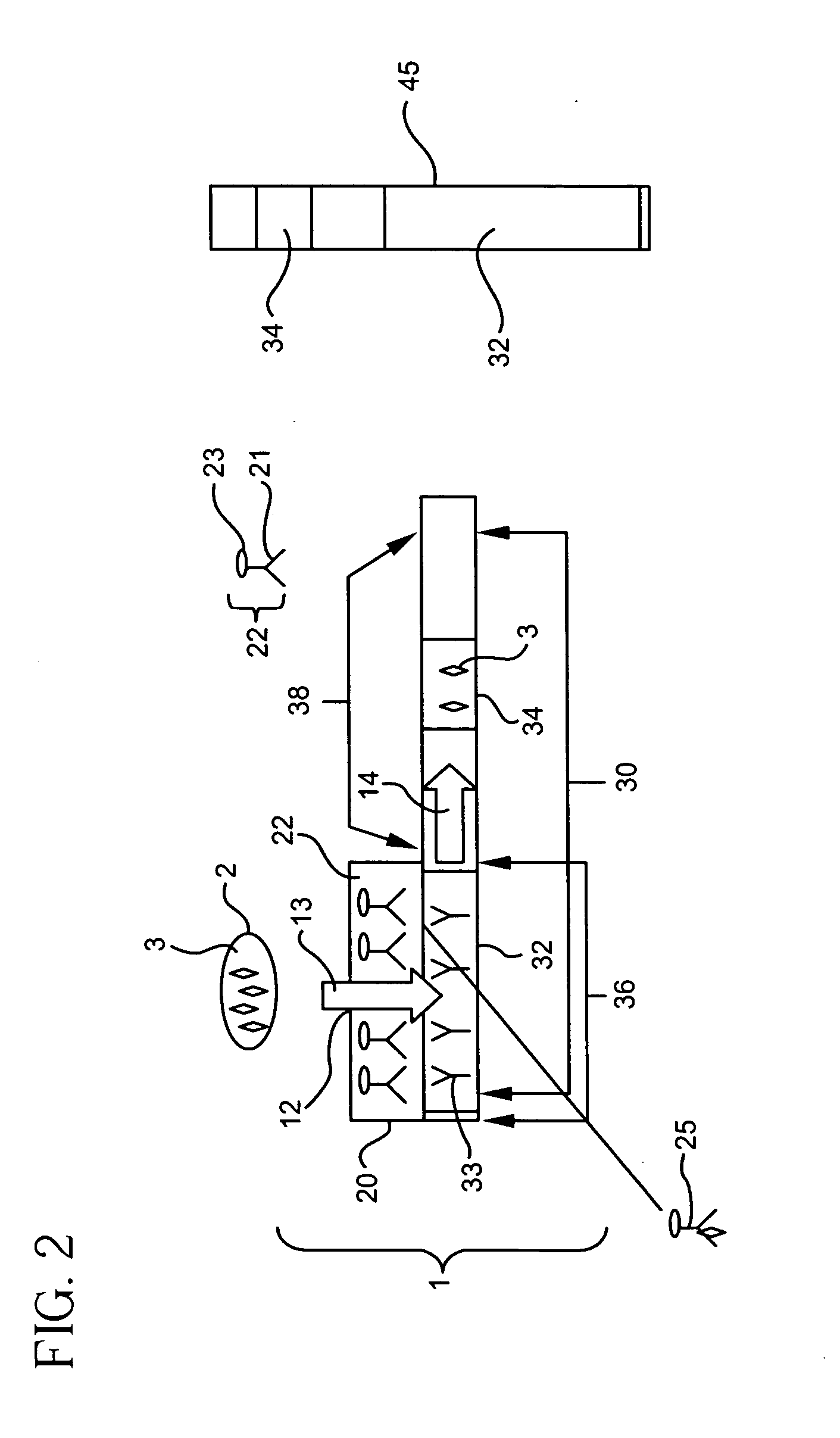
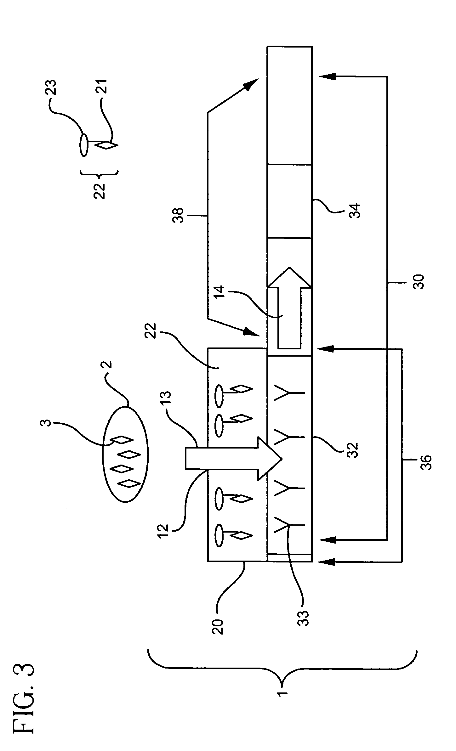
[0019] The second portion of the binder support medium is that part of the binder support medium that is not vertically juxtaposed with the tracer pad. This portion of the binder support medium may allow the liquid sample to laterally flow away from the detection zone. Labeled receptor moieties that are not bound to the analyte of interest or the immobilized binder may be cleared from the detection zone through the lateral flow of the liquid sample across the second portion of the binder support medium. This clearance of the unbound labeled receptor allows for the generation of a more accurate indication, eliminating or reducing the unbound labeled receptor from remaining in the detection zone.
[0026] The device may further comprise a supportive housing. This allows the device to be easily handled, prevents disturbance of the assay during use, and protects the components of the assay during shipment. The housing may comprise a window or aperture for applying the liquid sample, as well as a window or aperture for viewing the detection and control zones.
[0028] The invention provides a shorter distance an analyte must travel to encounter a detection zone because the liquid sample flows through the various pads to the detection zone in a vertical fashion as opposed to a lateral fashion. This may result in faster assays comprising less materials and a smaller size. Economical saving may be realized due to the reduced materials and smaller size, as well as potentially resulting in easier manufacturing. Because of the vertical aspects of the assay, the liquid sample may be exposed to a greater amount of tracer and binder, without experiencing the leading edge effects seen in strictly lateral flow assays. The invention can provide for a lateral flow away from the detection zone, and can result in an easily discernable indication from the detection zone as compared to vertical flow devices.

Problems solved by technology

In recent years, immunoassays have evolved from expensive and complex procedures requiring calibrated machinery and skilled technicians for operation to more simplistic designs such as dip-sticks and test strips using relatively inexpensive binder support mediums that are easily operated by anyone because they only require the user to follow a simple series of directions.
Reduced flow rates on a membrane may result in a leading or lagging edge effect on the membrane that cause uneven distribution of the complexes across the detection zone.
Such uneven distribution across the detection zone may lead to indicators in the detection zone that are difficult to read.
In addition, the distance the analyte-labeled receptor complex is required to travel prior to contact with the immobilized binder results in an increased analysis time.
Furthermore, many of the membranes utilized in lateral flow devices, such as nitrocellulose, may undesirably bind to the analyte of interest.
This undesirable binding may result in a dilution of the analyte given the long distances required for the analyte to travel in a lateral device before encountering the detection zone.
Dilution of the analyte can result in the reduced accuracy of the test device.
In addition, the vertical flow device reduces the unwanted binding of the analyte to the membranes utilized in the assays, due to the shorter distance of travel through the membrane.
Compared to lateral flow devices, the additional steps required of the operator with a vertical flow device can increase the error rate of the device.
In addition, analyzing the results of a flow through device may be more difficult than a lateral device if multiple pads are utilized in the flow through device because the detection zone may not be easily accessible.

Method used


Image

  • Combination vertical and lateral flow immunoassay device
  • Combination vertical and lateral flow immunoassay device
  • Combination vertical and lateral flow immunoassay device

Examples


example 1

[0146] a. Construction of Immunoassay Device

[0147] Immunoassay devices were constructed according to the present invention. In general, a tracer pad was placed directly on top of a binder support medium. The tracer pad was placed so that only a portion of the binder support medium was in direct contact with the tracer pad, leaving a portion of the binder support medium uncovered by the tracer pad. The tracer pad was placed directly over the portion of the binder support medium containing the detection zone. In addition, a sump pad was placed at the end of the binder support medium, allowing excess sample to flow from the binder support medium to the adjacent sump.

[0148]FIG. 16 is an overview of a representative schematic of the constructed immunoassay devices. Two immunoassay devices for the detection of a Respiratory Syncytial Virus (RSV) antigen were constructed. A nitrocellulose binder support medium 30 measuring 5.5×25 mm was removed from a Becton-Dickenson EZ RSV Kit (Catalog...


PUM


Abstract

The invention relates to immunoassays that detect the presence or absence, or determine the amount present of a particular analyte. More specifically, the invention relates to multizone, multilayered immunoassay test devices that utilize a combination of vertical and lateral flow to detect an analyte of interest.

Description

FIELD OF THE INVENTION [0001] The invention relates to immunoassays that detect the presence or absence, or determine the amount present of a particular analyte. More specifically, the invention relates to multizone, multilayered immunoassay test devices that utilize a combination of vertical and lateral flow to detect an analyte of interest. BACKGROUND OF THE INVENTION [0002] In vitro diagnostic (IVD) tests have revolutionized the rapid analysis of analytes, and allow for a simple and cost effective detection method for a myriad of moieties including proteins such as enzymes and hormones, drugs and drug metabolites, antibodies, and nucleic acids. Many of these tests are based on immunoassays that combine the principles of chemistry and immunology to provide for quantitative and qualitative analyses of target analytes. The basic principle of these assays is the detection of an analyte-receptor reaction. [0003] In recent years, immunoassays have evolved from expensive and complex pro...

Claims


Application Information

Patent Timeline
IPC IPC(8): G01N33/558
CPCG01N33/558G01N33/54386G01N33/54387
Inventor ROSENSTEIN, ROBERT W.
Owner BECTON DICKINSON & CO
Learn More