Geophone with mass position sensing

a technology of mass position and geophone, applied in the field of motion sensing elements, can solve the problems of reducing the effectiveness and quality of the geophone, imposing practical limits on the width of the useful frequency band of the geophone, and attempting to provide inertial mass displacement sensing, etc., to achieve the effect of increasing the effective surface area

Active Publication Date: 2007-09-27
INPUT OUTPUT INC
View PDF12 Cites 11 Cited by
  • Summary
  • Abstract
  • Description
  • Claims
  • Application Information

AI Technical Summary

Benefits of technology

[0014] In another aspect, all or a portion of the coil assembly is electrically coupled to the electrically conductive member for increasing an effective surface area of the electrically conductive member.
[0015] Another aspect provides an extended capacity plate electrically coupled to the electrically conductive member for increasing an effective surface area of the electrically conductive member.

Problems solved by technology

This displacement generally reduces the effectiveness and quality of the geophone.
Such displacement may also result from movement of the body to which the geophone is connected.
Consequently, performing and spring stiffness impose practical limits on the width of a geophone useful frequency band.
Attempts to provide inertial mass displacement sensing have heretofore proven difficult to implement in the manufacturing process for geophones due to the small size of today's geophone sensing element and the effect on sensitivity.

Method used


Image

  • Geophone with mass position sensing
  • Geophone with mass position sensing
  • Geophone with mass position sensing

Examples


Embodiment Construction

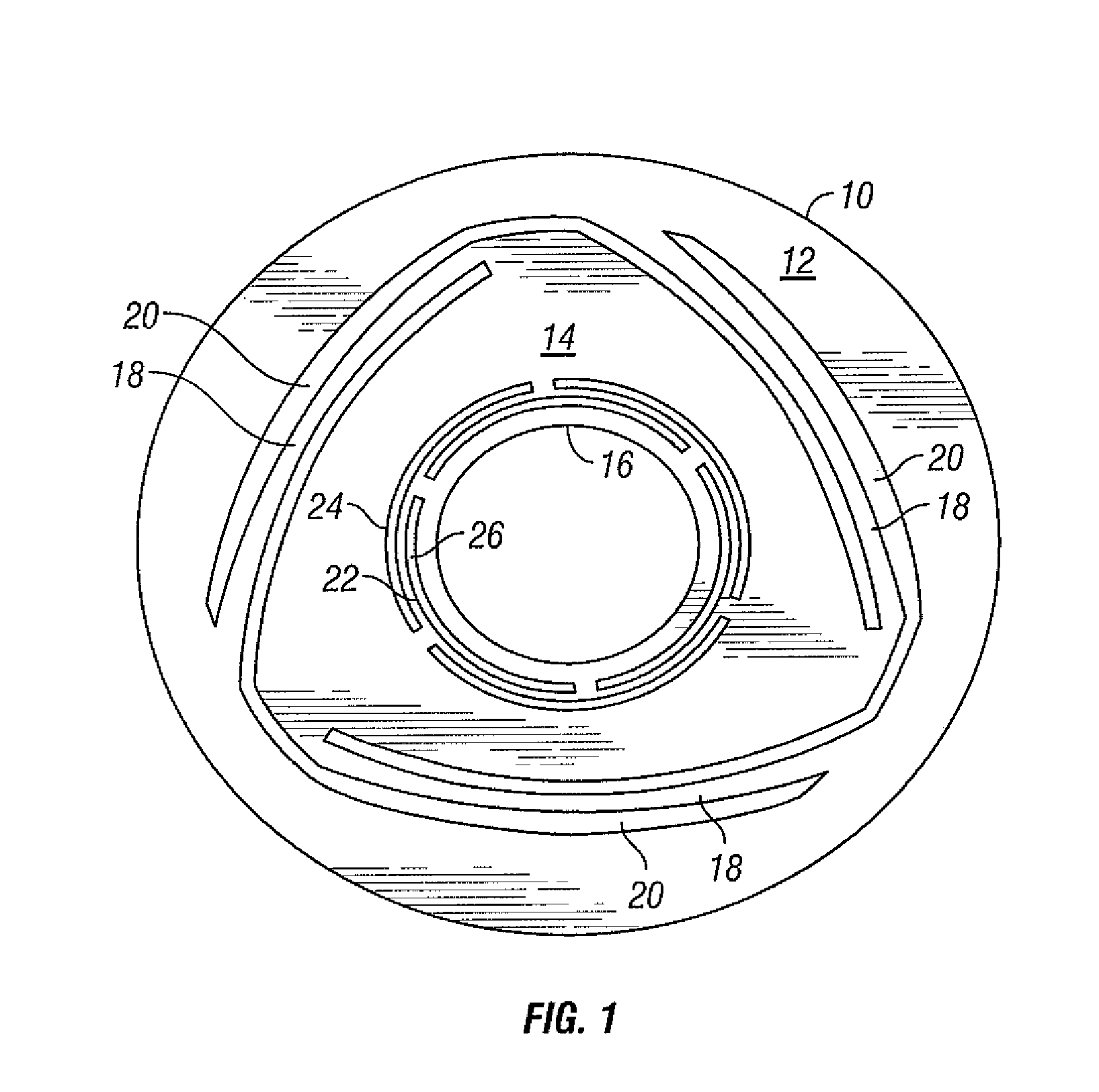
[0031]FIG. 1 is a non-limiting example of a sensor spring, which may be used in several sensing element examples of the present disclosure. The spring 10 may be manufactured using a thin, disc-shaped material such as beryllium copper.

[0032] The spring 10 comprises an outer spring which in turn has an outer ring member 12, a middle ring member 14, and an inner ring member 16. The outer ring member 12 and the middle ring member 14 are connected by a plurality of legs 18, which are formed by removing those portions of the disc designated 20. Preferably, this removal is effected by known etching techniques. The combination of the outer ring member 12, the middle ring member 14, and the legs 18 constitutes a first suspension means.

[0033] Still referring to FIG. 1, the spring 10 includes an inner spring which is formed between the middle ring member 14 and the inner ring member 16. The middle ring member 14 and the inner ring member 16 are connected by arms 22. The combination of the mi...


PUM


Abstract

A motion sensing element with position sensing includes a case, a magnet positioned within the case, a spring assembly having an electrically conductive member and a coil assembly coupled to the spring assembly. The coil assembly and magnet are moveable with respect to one another. A capacitor plate is proximate the electrically conductive member with a distance between the capacitor plate and electrically conductive member being variable as the magnet and coil assembly move. Leads connect the capacitor plate and electrically conductive member to a sensing circuit for estimating the relative positions of the magnet and coil assembly.

Description

CROSS REFERENCE TO RELATED APPLICATIONS [0001] This application is related to, and claims priority from, U.S. Provisional Patent Application Ser. No. 60 / 755,026 filed on Dec. 30, 2005 and titled Geophone with Mass Position Sensing, the entire specification of which is hereby incorporated herein by reference.BACKGROUND [0002] 1. Technical Field [0003] The present disclosure generally relates to motion sensing elements and more particularly to geophone sensing elements. [0004] 2. Background Information [0005] Geophones are used to sense motion in the earth. Geophones normally include a spring-mass sensing element to sense motion by suspending an inertial reference mass structure from a rigid, fixed supporting structure. Typically, the fixed supporting structure comprises an outer casing and a magnet, which is fixed inside the outer casing. This rigid, fixed supporting structure is typically fastened to the medium of which movement is to be measured using a housing structure including,...

Claims


Application Information

Patent Timeline
IPC IPC(8): G01V1/18
CPCG01V1/162G01V1/182G01V1/181
Inventor HAGEDOORN, AREND L.
Owner INPUT OUTPUT INC
Why Eureka
Try Eureka