Rack for containers

a technology for containers and racks, applied in the field of racks for holding water bottles, can solve the problems of relative movement, leaking containers, and leaking containers, and achieve the effect of reducing the damage of bottles during transportation and preventing movement and vibration

Inactive Publication Date: 2007-09-27
REHRIG PACIFIC CO INC
View PDF63 Cites 19 Cited by
  • Summary
  • Abstract
  • Description
  • Claims
  • Application Information

AI Technical Summary

Benefits of technology

[0010] When installed on a vehicle, a pump (or other air source) may be activated automatically whenever the door is closed and / or whenever the vehicle is shifted into gear (or when the engine is started). Activation of the pump inflates the expandable chambers, thereby locking containers in place in the bays. This prevents movement and vibration and reduces damage to the bottles during transportation

Problems solved by technology

Leaking containers are a problem within the existing system.
Testing has shown that the bouncing up and down of the bottles in the racks is a significant cause of leaking containers.
Whenever the truck is moving the rack and bottles experience vibration and therefore relative movement.
The movement at the contact points in combination with other environmental factors such as dirt and dust eventually weakens the bottle resulting in a hole or crack.
Testing has shown that the softer plastic racks can reduce this, but a push toward lighter and thinner bottles to reduce costs has made the problem significantly worse in recent years.
A drawback to this rack is the force required to effectively clamp all the bottles in a rack.
For a 40-bottle rack this results in a total locking force of 4000 lbs.
Cams and the length of the lever arm greatly reduce the input force needed from the driver but the force is still considerable.
Another problem with this design is that the locking force on individual bottles can vary by a large amount.
This is due to a fixed travel height for the tree that cannot adjust to the varying bottle sizes and shapes as well as pocket to pocket variances within the rack.
When the driver tries to lift the door the cap can jam against the raised corrugations on the inside of the door.
Much time and effort is required to solve this problem each time it occurs.
However, even with the existing clamping system, there is still the possibility that the driver will deliver bottles to the customer, then return to the truck and drive away while forgetting to clamp the bottles and close the door at all.
When this occurs, the bottles can fall out of the vehicle, littering the roadway and possibly causing damage to other vehicles.

Method used


Image

  • Rack for containers
  • Rack for containers
  • Rack for containers

Examples


first embodiment

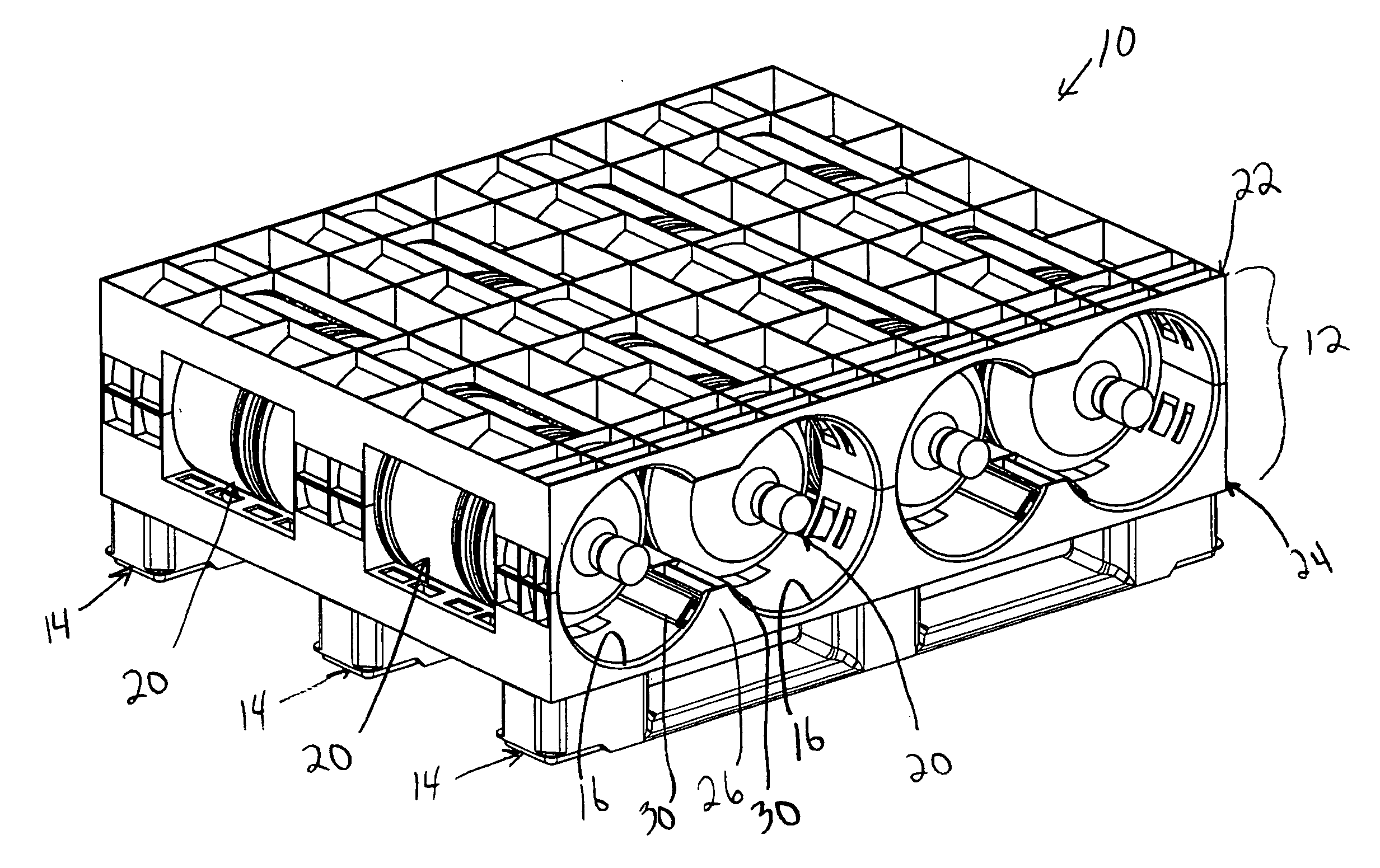
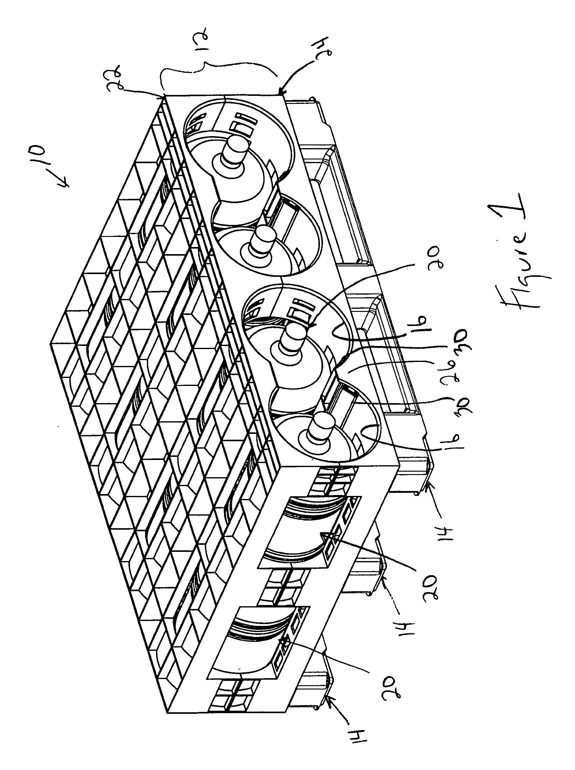
[0037] A rack 10 according to the present invention is shown in FIG. 1. The rack 10 includes a first layer 12 (or first “shelf”) supported on a plurality of supports 14. The first layer 12 defines a plurality of generally cylindrical bays 16. A pair of containers 20, in this case a pair of five gallon water bottles 20, can be received within each bay 16. The first layer 12 includes an upper section 22 and a lower section 24. The lower section 24 includes a partial divider 26 between each adjacent pair of bays 16. An expandable, inflatable clamping chamber 30 is mounted on each side of the divider 26 adjacent the bottles 20. The expandable chambers 30 are elongated, flexible pneumatic bladders or seals that extend from the front of the rack 10 to the rear of the rack 10.

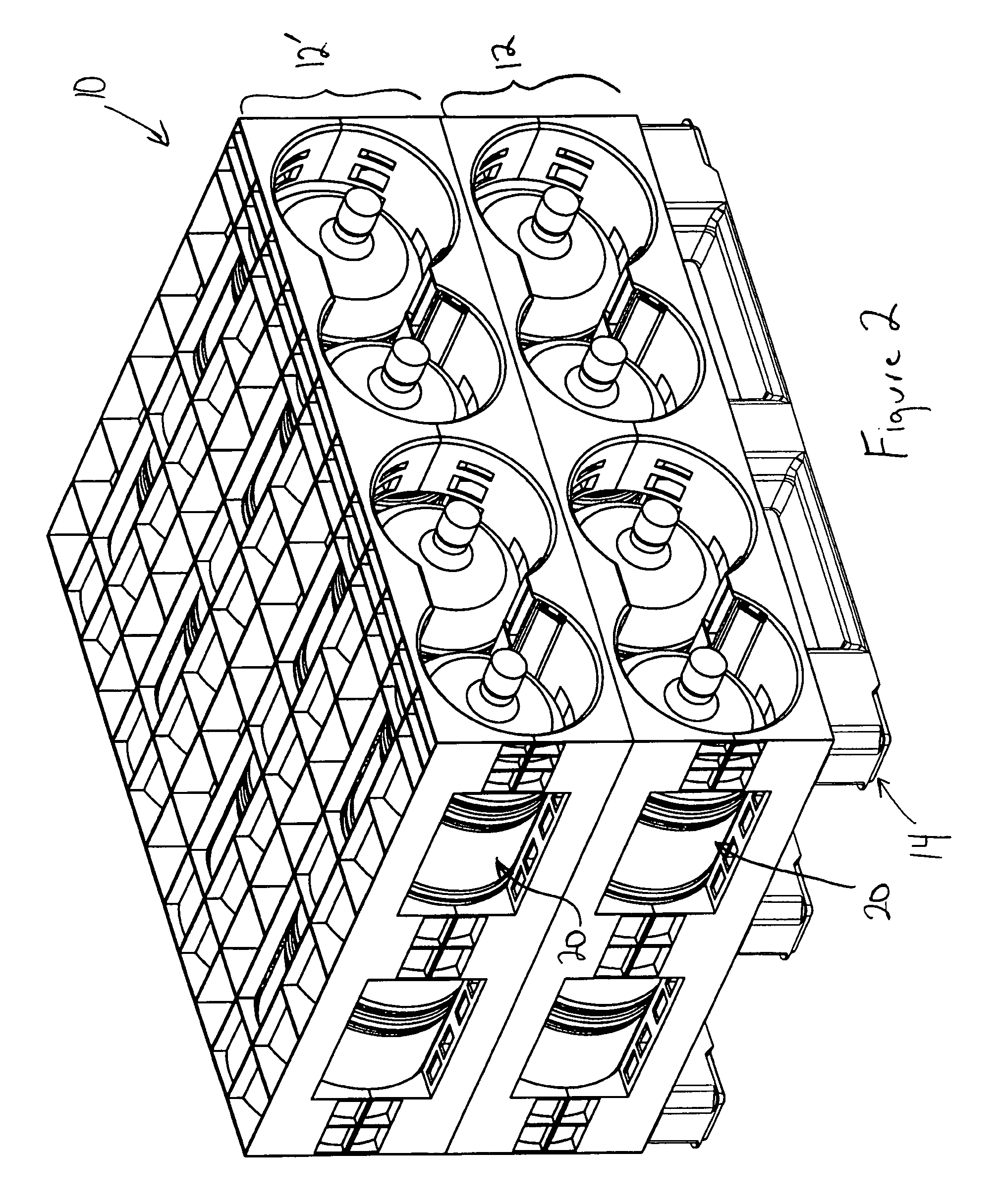
[0038] As shown in FIG. 2, the rack 10 can be expanded by adding additional shelves, such as a second layer 12′, stacked on top of the first layer 12. Both layers 12, 12′ are supported on the supports 14 above the flo...

second embodiment

[0049] A rack 110 is shown in FIG. 8. The rack 110 is similar to the rack 10 in structure and operation except as otherwise described below or shown in the drawings. Corresponding components will be designated with reference numerals prefixed with a “1.” In this rack 110, the expandable chamber 130 is positioned on top of the partial divider 126. As shown in FIG. 9, the mounting area 150 is formed on the top of the partial divider 126. FIG. 10 is a front view of the rack 110 with the expandable chambers 130 deflated. In this position the bottles 120 are not in contact with the expandable chamber 130 and can be easily inserted into or removed from the bays 116. Upon inflation of the expandable chambers 130 in the manner described above, the expandable chambers 130 each contact the bottles 20 in two adjacent bays 116 as shown in FIG. 11. This arrangement in the rack 110 reduces the total number of expandable chambers 130 that are necessary.

third embodiment

[0050]FIG. 12 illustrates a rack 210 according to a Except as otherwise described below or shown in the drawings, the rack 210 is similar in structure and operation to racks 10, 110. In this rack 210, the cylindrical bays 216 are defined on either side of the partial divider 226 and an expandable chamber 230 is provided for each bay 216. As shown in FIG. 13, the supports 214 snap-fit into the lower section 224 which in turn snap-fits into the upper section 222 for easy assembly of the rack 210.

[0051] Alternate arrangements and locations of the expandable chambers 30, 130, 230 are also possible. For example, the expandable chambers 30, 130, 230 may be placed on the upper halves 22, 122, 222 of the racks 10, 110, 210 so that the pressure exerted by the expandable chambers 30, 130, 230 is in the same direction as the gravity acting on the bottles 20. Alternatively, the expandable chambers 30, 130, 230 could be positioned inside or behind a wall of a rack section, such that expansion o...


PUM


Abstract

A rack for securing containers includes a plurality of bays into which one or more containers are received. An expandable, inflatable chamber is disposed adjacent each bay and selectively expands into the chamber to secure the containers within the bay. When installed on a vehicle, a pump may be activated automatically based upon a vehicle operating state or whenever the door is closed. Activation of the pump inflates the expandable chambers, thereby locking containers in place in the bays. This prevents movement and vibration and reduces damage to the bottles during transportation

Description

BACKGROUND OF THE INVENTION [0001] The present invention relates generally to a rack for holding objects and more particularly to a rack for holding water bottles. [0002] A typical home delivery system for 3 and 5-gallon bottles of drinking water involves a delivery truck, racks, bottles and a driver. The delivery truck is usually configured with several bays on each side with each bay having a rollup door to enclose the product. Inside each bay one or more racks are stored filled with bottles. The racks are typically loaded and unloaded with bottles outside the bays. Fork trucks are used to move the racks in and out of the bays. [0003] The racks have traditionally been made from metal and more recently from plastic. The plastic racks tend to be modular in design with each component making up a layer of the rack. The layer can hold four bottles in a two by two arrangement or eight bottles in a four wide by two deep arrangement. A two deep arrangement is for 5-gallon bottles whereas ...

Claims


Application Information

Patent Timeline
Patent Type & Authority Applications(United States)
IPC IPC(8): A47B73/00
CPCB60P3/055B65D19/44B65D2519/00034B65D2519/00069B65D2519/00965B65D2519/00323B65D2519/00333B65D2519/00567B65D2519/00815B65D2519/00288
Inventor APPS, WILLIAM P.
Owner REHRIG PACIFIC CO INC
Why Eureka
Try Eureka