
Water pump with housing/impeller to enhance seal performance

a technology of water pump and seal, applied in the direction of machines/engines, stators, liquid fuel engines, etc., to achieve the effect of increasing static pressure, enhancing seal performance, and reducing coolant velocity

Active Publication Date: 2007-09-20
FORD GLOBAL TECH LLC
View PDF11 Cites 13 Cited by
  • Summary
  • Abstract
  • Description
  • Claims
  • Application Information

AI Technical Summary

Benefits of technology

[0006] The present invention provides systems and methods for improving seal performance by increasing static pressure within a seal cavity of the housing of a centrifugal water pump for an internal combustion engine. Embodiments of the invention use impeller and seal cavity design features positioned to convert dynamic or total pressure into static pressure at the seal while also reducing coolant velocity at the seal.
[0009] The present invention provides a number of advantages. For example, the present invention recognizes the effect of static pressure in the seal environment on seal performance and enhances seal performance by increasing static pressure at the seal relative to prior art designs. The present invention reduces coolant velocity at the seal, which increases static pressure and enhances seal performance. Positioning of ribs in the pump housing inside the seal cavity according to the present invention disrupts the induced circular coolant flow pattern and lowers coolant velocity at the seal to enhance seal performance. Use of design features, such as ribs and slots, within the seal cavity according to the present invention improves robustness of the pump assembly in that the pressure rise from the inlet to the stationary part of the seal is less sensitive to axial distance between the impeller and housing due to manufacturing / assembly tolerances and / or movement during operation.

Problems solved by technology

Ribs increase the static pressure at the seal by disrupting the circular flow pattern induced by rotational impeller motion during operation.

Method used


Image

  • Water pump with housing/impeller to enhance seal performance
  • Water pump with housing/impeller to enhance seal performance
  • Water pump with housing/impeller to enhance seal performance

Examples


Embodiment Construction

)

[0022] As those of ordinary skill in the art will understand, various features of the present invention as illustrated and described with reference to any one of the Figures may be combined with features illustrated in one or more other Figures to produce embodiments of the present invention that are not explicitly illustrated or described. The combinations of features illustrated provide representative embodiments for typical applications. However, various combinations and modifications of the features consistent with the teachings of the present invention may be desired for particular applications or implementations.

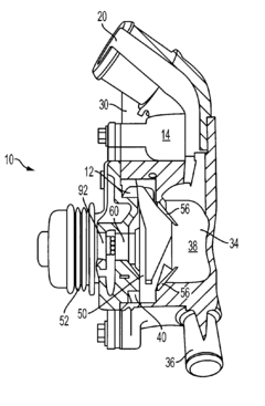
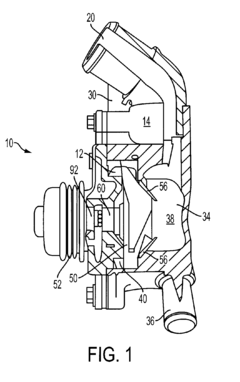
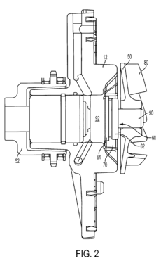
[0023] Referring now to FIG. 1, a cut-away view of a centrifugal water pump assembly 10 for an automotive internal combustion engine application includes a housing cover 12 secured to a housing base 14 by a plurality of fasteners. Depending on the particular application and implementation, the housing base and / or cover may be integrally formed within another engine c...


PUM


Abstract

Systems and methods for improving seal performance in a centrifugal water pump for an internal combustion engine increase static pressure at the seal by incorporating a combination of slots and ribs into a seal cavity of the pump housing that are positioned to convert dynamic fluid pressure into static pressure at the seal while reducing coolant velocity at the seal. Vent holes in the impeller having an appropriate size and location may also be used to increase the static pressure at the seal to enhance seal performance.

Description

BACKGROUND OF THE INVENTION [0001] 1. Field of the Invention [0002] The present invention relates to systems and methods for enhancing water pump seal performance in a water / coolant pump for an internal combustion engine. [0003] 2. Background Art [0004] Internal combustion engines typically have a liquid cooling system that uses a water pump to circulate engine coolant between a radiator and the cooling water jacket of the engine. A typical centrifugal water pump consists of a shaft mounted impeller rotatable inside a housing. The shaft is substantially part of an integrated shaft bearing which is pre-lubricated and located in an environment free of debris and coolant. A mechanical seal with sliding faces is disposed about the shaft and mounted in the housing inside a seal cavity behind the impeller to prevent leakage of coolant into the area where the bearings support the shaft and / or outside of the housing. The mechanical seal relies on a lubricating fluid film to inhibit or preve...

Claims


Application Information

Patent Timeline
Patent Type & Authority Applications(United States)
IPC IPC(8): F04D29/44
CPCF04D29/128
Inventor SLIKE, JODYYU, PAUL PO-WENHERTRICH, PATRICK
Owner FORD GLOBAL TECH LLC
Learn More