
Microwave Heating Method And Device Therefor

a microwave and heating method technology, applied in the field of microwave heating methods and apparatuses, can solve the problems of the tendency to increase the temperature difference between icy and thawed portions, and the coexistence of partially cooked and unthawed portions, so as to reduce the heating of objects, the effect of enhancing the finished state of the object to be heated and restrainting local heating peculiar to microwave heating

Inactive Publication Date: 2007-09-20
PANASONIC CORP
View PDF4 Cites 53 Cited by
  • Summary
  • Abstract
  • Description
  • Claims
  • Application Information

AI Technical Summary

Benefits of technology

[0029] According to the microwave heating method and apparatus of the invention, the minute particles of water are supplied into the heating chamber to change the permittivity distribution state of the interior of the heating chamber, thereby changing the electric field distribution of the interior of the heating chamber provided by microwaves supplied into the heating chamber. Thanks to this, the local heating peculiar to the microwave heating can be restrained and thus the heating of the object to be heated can be made uniform, resulting in the enhanced finished state of the object to be heated after heated.

Problems solved by technology

In other words, while the heating of the icy portion of the object to be heated is slow, the heating of the thawed portion thereof is accelerated, with the result that there is a tendency to increase a difference in temperature between the icy and thawed portions.
Thus, in the object to be heated, there occur local heating phenomena outstandingly, resulting in a problem that a partially-cooked portion and an unthawed portion coexist together.
However, even with use of these methods, especially, when thawing a frozen food, there cannot be always obtained a satisfactory result but, depending on heating conditions, the temperature distribution increases, which results in the above-mentioned partially cooked phenomenon.

Method used


Image

  • Microwave Heating Method And Device Therefor
  • Microwave Heating Method And Device Therefor
  • Microwave Heating Method And Device Therefor

Examples


second embodiment

[0135] Next, description will be given below of a microwave heating apparatus according to the invention.

[0136]FIG. 21 shows a schematic structure view of a microwave heating apparatus according to the second embodiment of the invention.

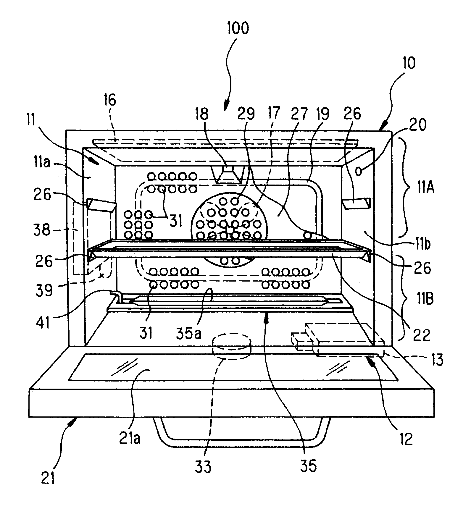
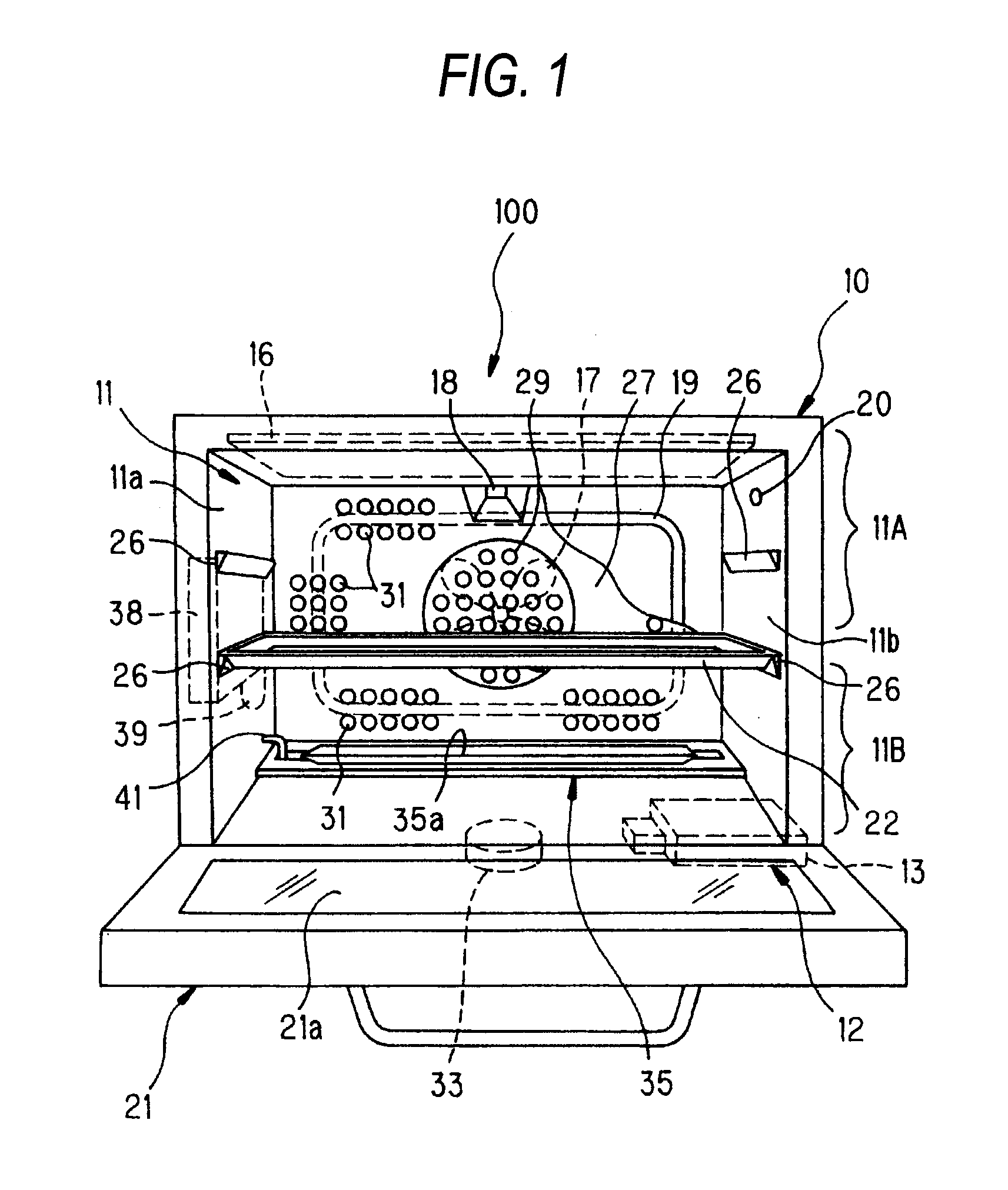
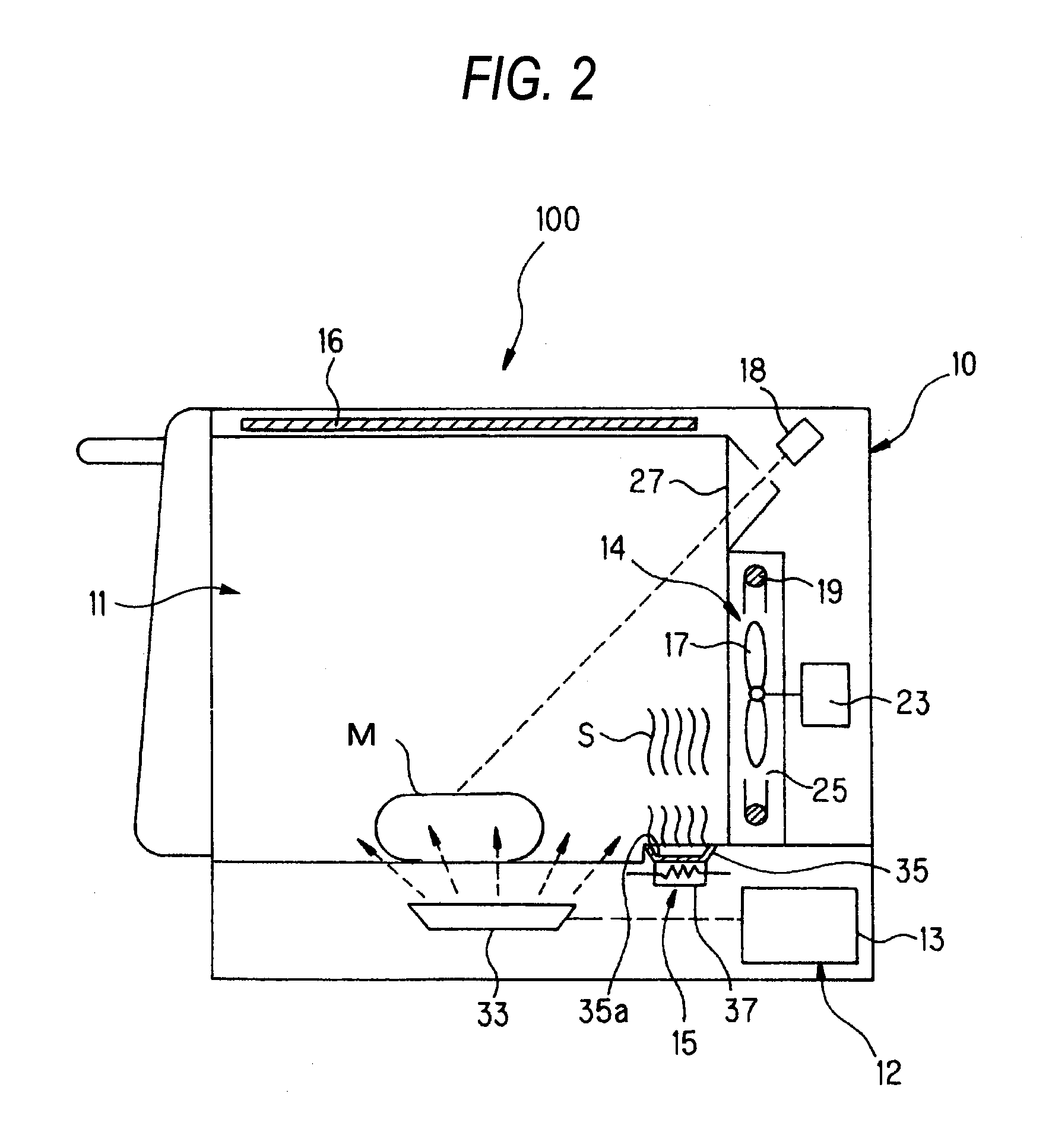
[0137] In a microwave heating apparatus 200 according to the present embodiment, the steam supply part 15 is structured such that it guides steam generated in the evaporation dish 35 out of the heating chamber 11 once and blows the steam from above the heating chamber 11 through an external pipe 81 into the heating chamber 11 again. Also, on the heating chamber 11, there is mounted a tray 83 made of ceramics, resin, glass or the like which transmits microwaves, while a space within the heating chamber 11 is vertically divided by the tray 83 into upper and lower section spaces.

[0138] According to this structure, steam is supplied to the upper section space 11A of the heating chamber 11, so that only the upper section space 11A is filled with the ste...

first embodiment

[0139] By the way, the steam generating means is not limited to a power heating type of steam generating means for heating the evaporation dish 35 including a structure but, for example, there may also be used a boiler type of steam generating means. However, when the influence of impurities contained in water and the maintenance of the structure are taken into account, preferably, there may be used a structure in which the evaporation dish 35 is disposed within the heating chamber 11 in an exposed manner. With use of this structure, it is easy to remove scales which stick to the evaporation dish 35 when steam is generated; and, therefore, this structure is excellently sanitary. Also, there may also be employed a drop type structure in which a valve of a water supply passage is opened to drop water drops down to a heating member to thereby generate steam. In this case as well, there can be obtained a similar effect to the case of the evaporation dish 35.

[0140] And, by combining tog...

third embodiment

[0141] Next, description will be given below of a microwave heating apparatus according to the invention.

[0142]FIG. 22 shows a schematic structure view of a microwave heating apparatus according to the third embodiment of the invention.

[0143] In a microwave heating apparatus 300 according to the present embodiment, the steam supply part 15 is structured such that, instead of use of steam obtained by heating water, it includes mist supply means 87 for supplying mist-like water drops into the heating chamber 11. According to this structure, mist-like water drops of a minute size (mists) are supplied into the heating chamber 11. It is considered that the larger the size of the mist is, the greater the effect of changing the electric field distribution of a microwave is. Therefore, the size of the mist may be set larger than the ordinary size of the mist, 3 μm, preferably, it may be set for 10 μm or larger, more preferably, in the range of 25 μm-100 μm, with the result that the suffici...


PUM


Abstract

The problem to be solved by the invention is to restrain local heating peculiar to microwave heating to thereby realize the uniform heating of an object to be heated and thus enhance the condition of the object to be heated after heated. In a microwave heating method for supplying microwaves into a heating chamber 11 storing therein an object to be heated to heat the object to be heated, microwaves are supplied into the heating chamber 11 to heat the object to be heated; the temperature of the object to be heated is measured to check whether a given temperature difference has been generated in the temperature distribution of the object to be heated; and, when the given temperature difference has been generated, the minute particles of water are supplied into the heating chamber 11 to change the permittivity distribution state within the heating chamber 11, thereby changing the distribution of electric fields caused by the microwaves supplied into the heating chamber 11.

Description

TECHNICAL FIELD [0001] The present invention relates to microwave heating method and apparatus for dielectrically heating an object to be heated. BACKGROUND ART [0002] In a microwave oven which is a representative of a microwave heating apparatus, microwaves radiated from a magnetron are transmitted through a waveguide to a heating chamber to form standing waves within the heating chamber, and an object to be heated is caused to generate heat according to the electric field component of the standing waves and the dielectric loss of the object to be heated. Power P [W / m3], which is absorbed by the object to be heated per unit volume, can be expressed by the following equation: That is, P=(5 / 9) εr·tan δ·f·E2×10−10 [W / m3], where E[V / m] expresses the intensity of an electric field applied, f[Hz] expresses a frequency, εr expresses the relative permittivity (the real number portion of the permittivity) of the object to be heated and tan δ expresses the dielectric loss tangent of the obje...

Claims


Application Information

Patent Timeline
IPC IPC(8): H05B6/64F24C1/04F24C7/02F24C15/32H05B6/68H05B6/74
CPCF24C1/04F24C15/327H05B6/74H05B6/687H05B6/704H05B6/6479F24C1/14
Inventor YOSHINO, KOJINOBUE, TOMOTAKAINADA, IKUHIRO
Owner PANASONIC CORP
Learn More