
Ultra low power system for sensor network applications

a sensor network and ultra-low power technology, applied in the direction of power management, high-level techniques, instruments, etc., can solve the problems of limited application space, unable to meet the needs of users, and built using commodity chips, so as to achieve sufficient performance, reduce clock rates, and reduce the effect of cycle counts

Inactive Publication Date: 2007-09-13
PRESIDENT & FELLOWS OF HARVARD COLLEGE
View PDF21 Cites 28 Cited by
  • Summary
  • Abstract
  • Description
  • Claims
  • Application Information

AI Technical Summary

Benefits of technology

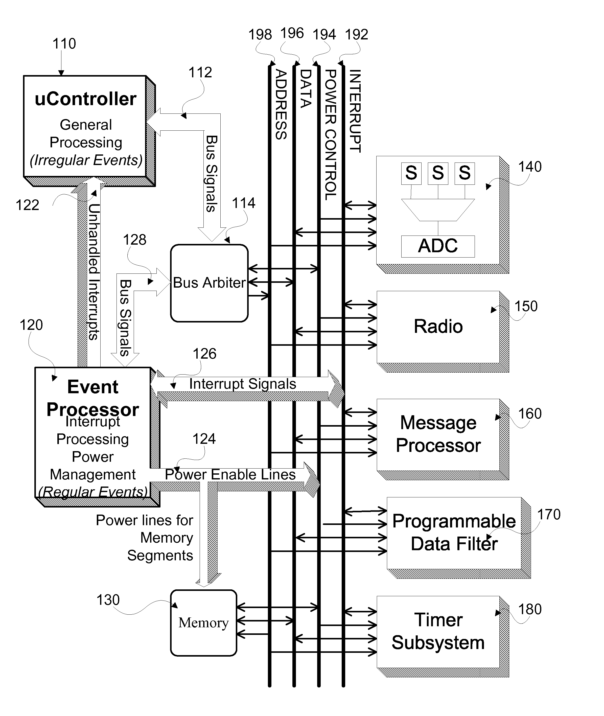
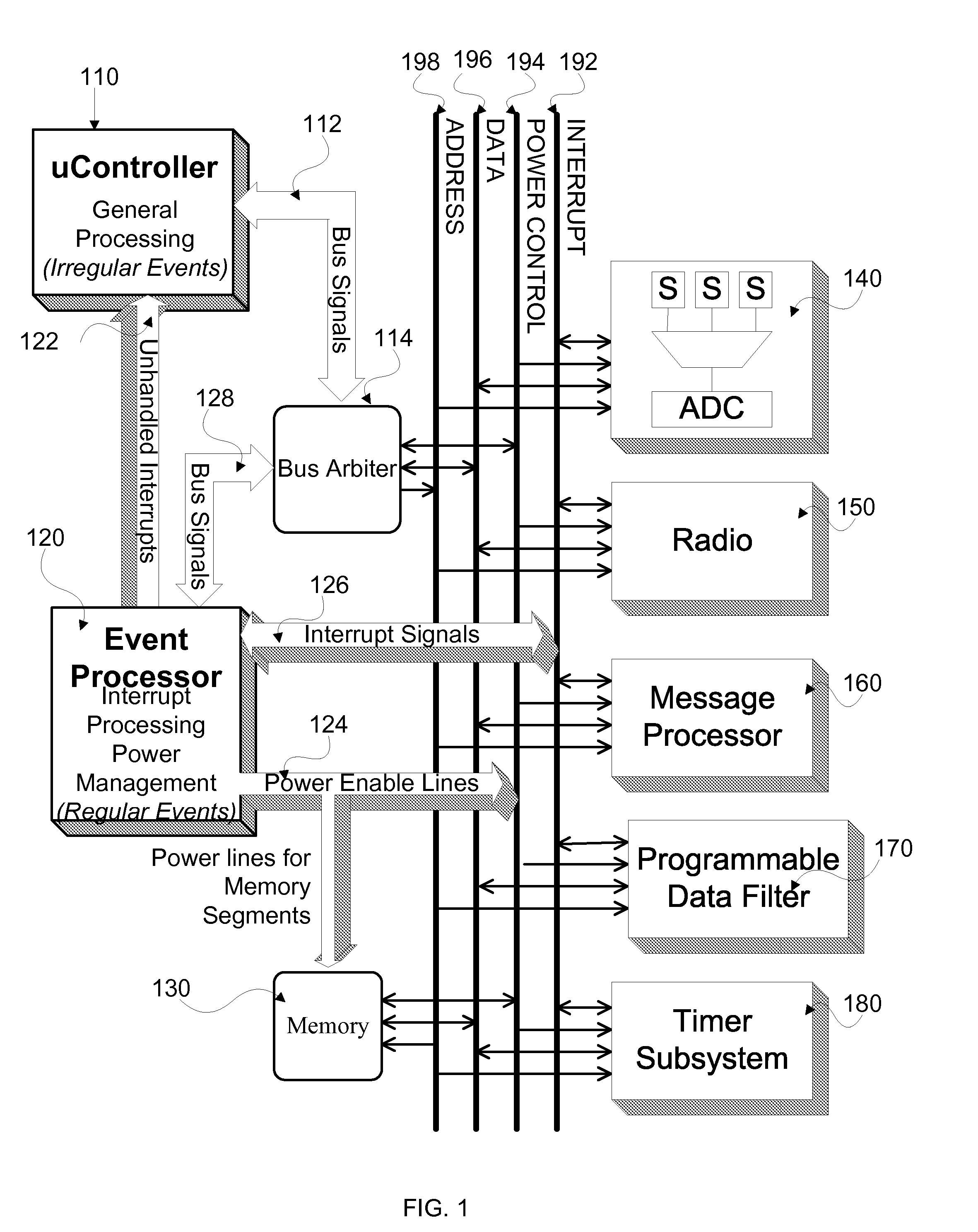
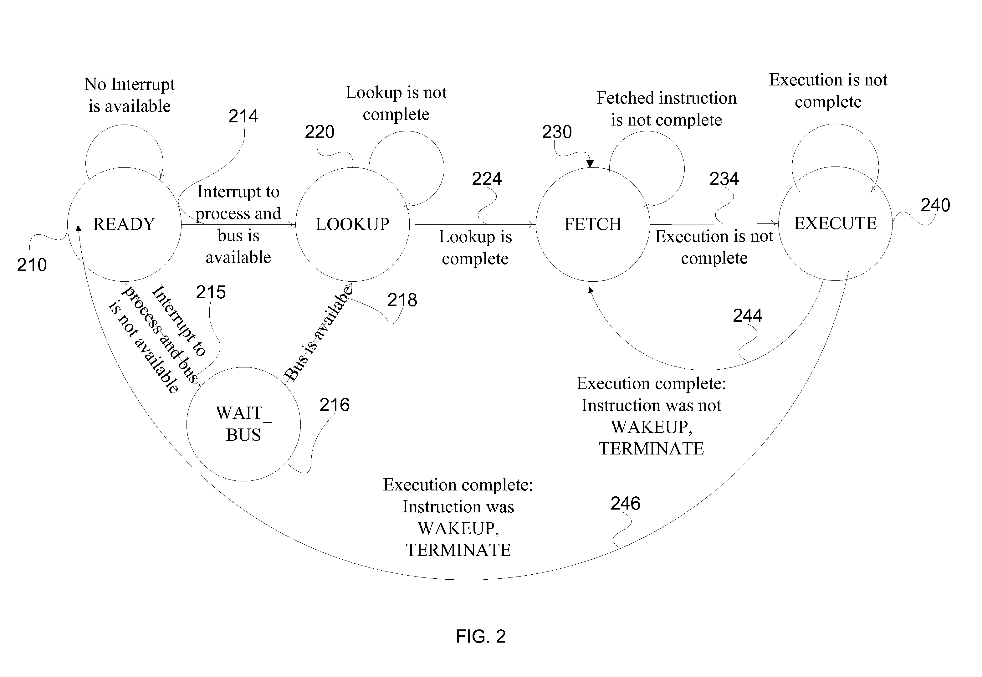
[0076] It is clear that the emphasis of our proposed architecture, for typical events seen within a sensor node, has significant cycle-count advantages over commodity systems. These advantages enable our architecture to operate at significantly lower clock rates while maintaining sufficient performance to keep up with the 802.15.4 radio standard and process sensor data requests at a level required by typical applications.

Problems solved by technology

While the application space seems limitless, it is actually limited by the operating lifetime of the battery-operated wireless sensor nodes.
One of the main limitations of these platforms is that they are built using commodity chips, which themselves are not specifically designed for wireless sensor networks.
As a result, they suffer several inefficiencies that lead to high power consumption and limited operational lifetimes.
In these systems, the CPU, radio, and sensor devices are responsible for the majority of the total system power and we show that the general purpose nature of commodity microcontrollers results in inefficient power usage, presenting an opportunity to significantly reduce its power.
The devices that have been used widely for research and in some commercial deployments, such as the Mica2 and Telos (J. Polastre, R. Szewczyk, C. Sharp, and D. Culler, “The Mote Revolution: Low Power Wireless Sensor Network Devices,”In Hot Chips 16: A Symposium on High Performance Chips, August 2004) motes, employ general-purpose microcontrollers that do not efficiently handle interrupt processing.
However, the primary task of a sensor network device is to handle timer and external interrupts since their applications are inherently event driven (J. Hill, “System Architecture for Wireless Sensor Networks,” PhD thesis, UC Berkeley, May 2003).
However, the SNAP architecture does not exploit the powerful event-driven paradigm apart from getting rid of the TinyOS overhead.
In other words, its primary computing engine is still a general purpose microcontroller that must remain powered on all the time, even when events occur rarely, thereby incurring leakage power.
All known architectures for wireless sensor network devices fail to optimize common-case behavior of applications, because they all suffer from the overly general purpose nature of the primary computing engines.

Method used


Image

  • Ultra low power system for sensor network applications
  • Ultra low power system for sensor network applications
  • Ultra low power system for sensor network applications

Examples


Embodiment Construction

[0019] In contrast to the prior systems, the present invention seeks to fully leverage the event-driven nature of applications in the design of next generation low-power sensor network nodes. Scavenging energy from the environment and using this energy to power the sensor network device greatly increases the effective lifetime of a wireless sensor node.

[0020] There are many sources of energy available in the environment such as solar, vibration, and electromagnetic radiation, and researchers have developed techniques to harness this energy (S. Roundy, P. K. Wright, and J. Rabaey, “A study of low level vibrations as a power source for wireless sensor nodes,”Computer Communications, 26(1):1131-1144, July 2003 ). For example, vibrational energy can be translated into electrical energy through piezoelectric materials that induce an open circuit voltage when placed under mechanical stress. While using vibration as an energy source is promising, the power output is limited to the order o...


PUM


Abstract

A system for sensor network applications comprising a microcontroller for handling irregular events, at least one hardware accelerator for handling regular events, an event processor for interrupt handling and power management in the system, and a system bus. The microcontroller, hardware accelerator, and event processor each are connected to the system bus. The event processor gates power to the microcontroller to provide power to the microcontroller only for processing related to irregular events requiring processing by the microcontroller. The event processor further may gate power to the hardware accelerator. The system may further include a message processor and a plurality of sensors.

Description

CROSS-REFERENCE TO RELATED APPLICATIONS [0001] The present application claims the benefit of the filing date of U.S. Provisional Application Ser. No. 60 / 781,929 entitled “An Ultra Low Power System Architecture for Sensor Network” and filed on Mar. 13, 2006. [0002] The above cross-referenced related application is hereby incorporated by reference herein in their entirety.STATEMENT REGARDING FEDERALLY SPONSORED RESEARCH OR DEVELOPMENT [0003] This work was supported by National Science Foundation Grant No. 0330244. BACKGROUND OF THE INVENTION [0004] 1. Field Of The Invention [0005] The present invention relates to the architectural design and implementation of wireless sensor devices. [0006] 2. Brief Description Of The Related Art [0007] Wireless sensor networks are poised to transform the way society interacts with the physical world, driven by an explosion of systems research in sensor networks. Sensor networks have been proposed and deployed for a wide variety of applications such a...

Claims


Application Information

Patent Timeline
Patent Type & Authority Applications(United States)
IPC IPC(8): G06F1/00
CPCH04W84/18H04W52/028Y02D30/70
Inventor HEMPSTEAD, MARKTRIPATHI, NIKHILMAURO, PATRICK GERARD IIWEI, GU-YEONBROOKS, DAVID
Owner PRESIDENT & FELLOWS OF HARVARD COLLEGE
Learn More