Universal clock generator using delay lock loop

Inactive Publication Date: 2004-09-28
MICREL
View PDF8 Cites 28 Cited by
  • Summary
  • Abstract
  • Description
  • Claims
  • Application Information

AI Technical Summary

Benefits of technology

The clock generator according to the first embodiment may also comprise a token generator that receives the output clock signal from the sequencer and generates control signals for controlling the sequencer. The control signals generated by the token generator control the sequencer to select only one of the delayed clock signal at each cycle of the output clock signal according to the predetermined sequence. The clock generator may also include a divide-by-2 circuit that receives the output clock signal from the sequencer, reduces the output clock frequency in half, and acdjusts the duty cycle of the output clock signal to fifty percent.
The present invention also provides a method of generating an output clock signal using a delay lock loop and a sequencer. The method receives an input clock signal having an input clock frequency and generates a plurality of delayed clock signals each having a frequency same as the input clock frequency but a different phase delay in relation to the input clock signal. The method selects one of the delayed clock signals at any moment according to a predetermined sequence to generate the output clock signal having an output clock frequency corresponding to the predetermined sequence. The method may also reduce the output clock frequency in half and adjust the duty cycle of the output clock signal to fifty percent.
The clock generator according to the present invention has the advantage that it is capable of generating very versatile clock signals having different frequencies by use of a plurality of delayed clock signals output from the DLL having different phase delays in a controlled way to select the delayed clock signals according to different sequences. the frequency of the output clock signal is controlled by the sequence in which the clock signals are selected.

Problems solved by technology

However, conventional clock generators have the disadvantage that it is difficult to control the duty cycles of the clocks generated and that multiple clock generators are sometimes required to generate clock signals with different frequencies.
For example, the duty cycles of the clocks generated by a conventional digital divider are difficult to control, because they are limited to the integer divider numbers of the digital dividers generating the clocks.
Furthermore, PLLs are not amenable to generating clocks of high frequency since they have to run at an even higher frequency and then their output signals have to be divided down by an integer to the desired clock frequency.

Method used


Image

  • Universal clock generator using delay lock loop
  • Universal clock generator using delay lock loop
  • Universal clock generator using delay lock loop

Examples


Embodiment Construction

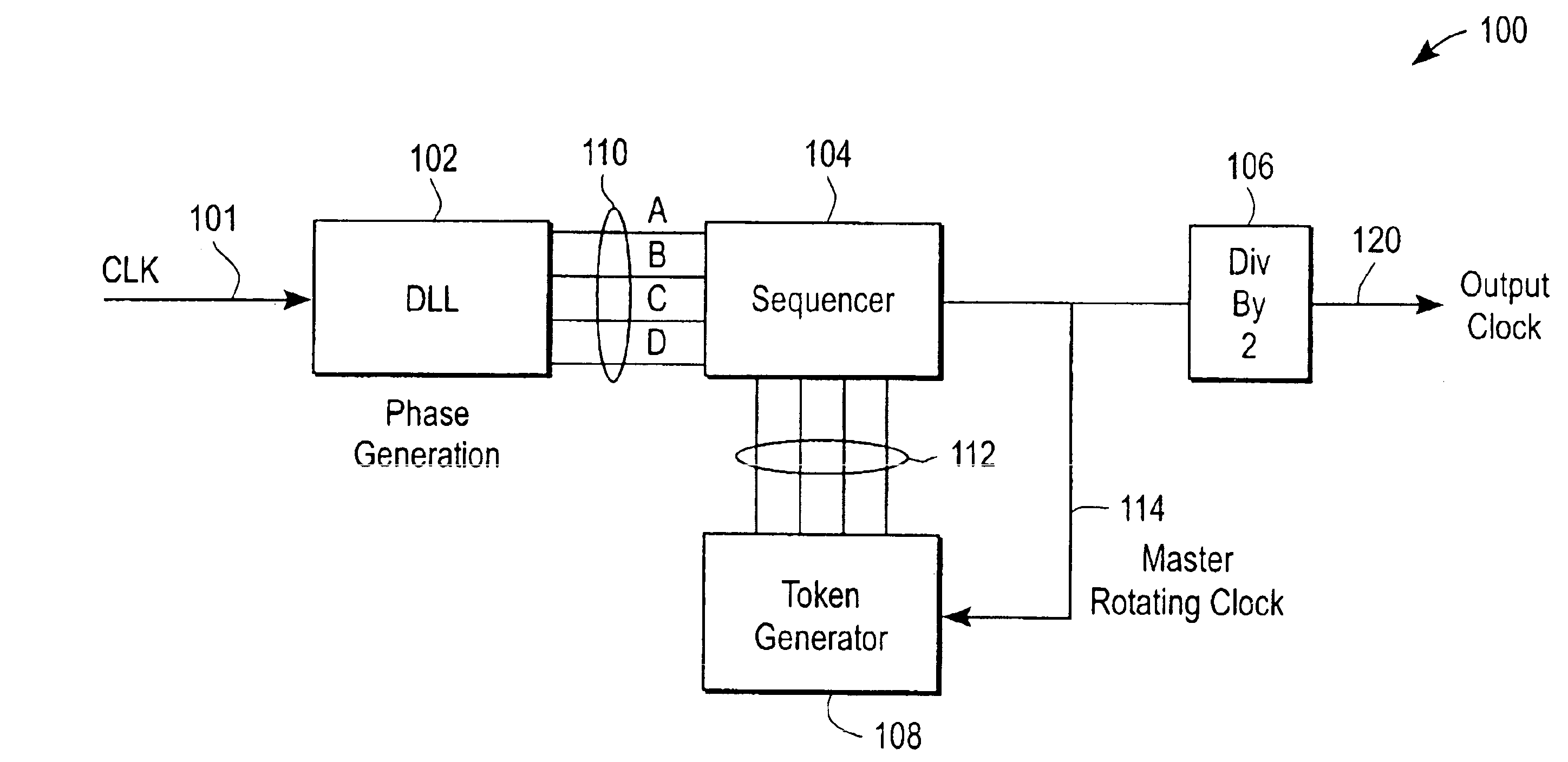
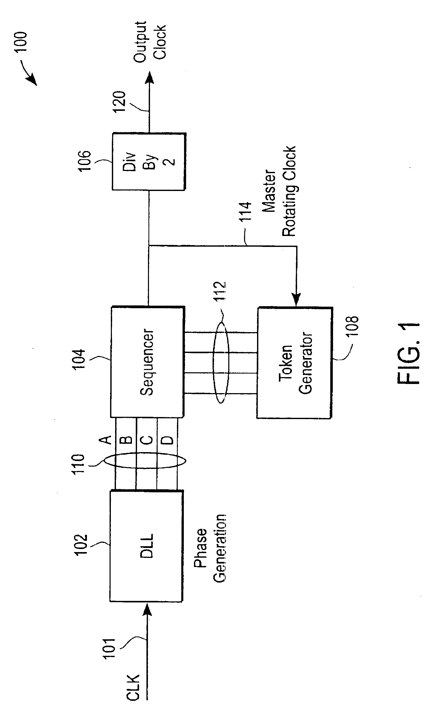
Referring now to the block diagram of FIG. 1, the universal clock generator 100 is capable of generating clock signals of a variety of frequencies with 50% duty cycles, comprises a Delay Lock Loop phase (DLL) 102, a sequencer 104, a divide-by-2 circuit 106, and a token generator 108.

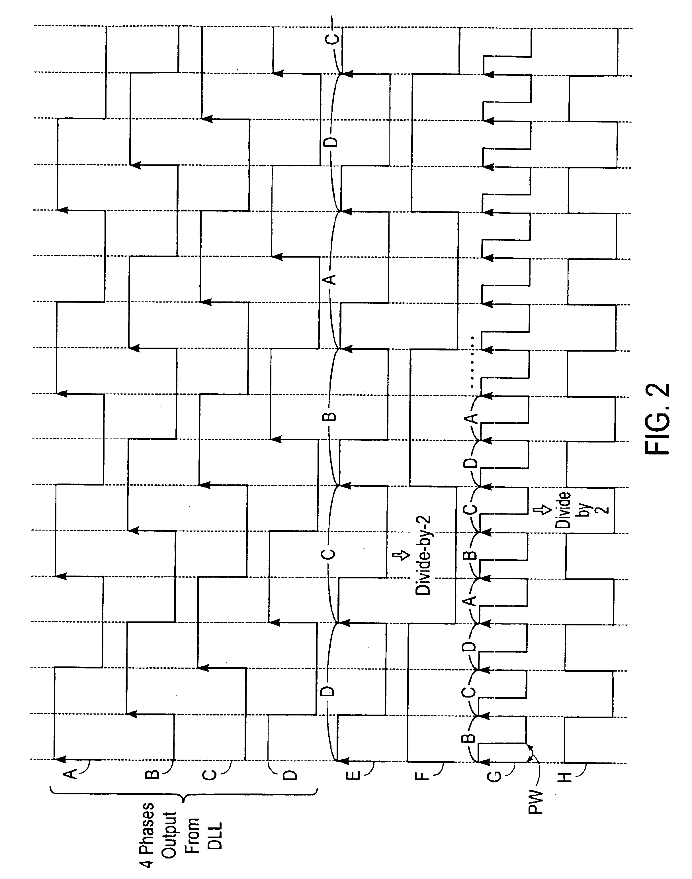
The DLL 102 receives an incoming clock signal 101, locks to the incoming clock 101, and generates a plurality of delayed clock signals 110 based on the incoming clock signal 101. The delayed clock signals 110 have the same frequency as that of the incoming clock signal 101, but are delayed by different delay phases (A, B, C, D). These multiple phases (A, B, C, and D) have finite delays. For example, the delayed clock signals 110 may include 4 delayed clock signals (A, B, C, and D) that are each delayed by different phases, such as different integer multiples of 90 degrees. Although FIG. 1 shows four delayed clock signals 110 output from the DLL 102, it should be noted that any number of delayed clock sig...


PUM


Abstract

A clock generator and method generates a plurality of clocks of different frequencies using a delay lock loop and a sequencer. The delay lock loop receives an input clock signal having an input clock frequency and generates a plurality of delayed clock signals each having a frequency same as the input clock frequency and a different phase delay in relation to the input clock signal. The sequencer receives the delayed clock signals and selects one the delayed clock signals at any moment according to a predetermined sequence to generate an output clock signal having an output clock frequency corresponding to the predetermined sequence. The frequency of the output clock signal is controlled by the sequence in which the delayed clock signals are by the sequencer.

Description

The present invention relates generally to clock generators used in integrated circuits, and more particularly to a universal clock generator using a delay lock loop to generate multiple frequencies of clocks for integrated circuits.Clock generators are widely used in digital integrated circuits to generate clock signals for synchronizing the operation of various components in digital circuits at the frequency of the clock. The components in the digital circuits typically synchronize their operation with one another at the rising edges or falling edges of the clock signals.Certain components in digital circuits may require operation at frequencies different from those required in other components. In such cases, digital circuits typically include a plurality of clock generators for generating clock signals at different frequencies.Conventional clock generators use a phase-locked-loop (PLL) scheme and / or a digital divider to generate clock signals. However, conventional clock generat...

Claims


Application Information

Patent Timeline
IPC IPC(8): G06F1/06H03L7/08H03L7/081
CPCG06F1/06H03L7/0812
Inventor VU, CUNGCHANG, MENPINGCHEN, JUNE-YING
Owner MICREL
Why Eureka
Try Eureka