Wavelength selective optical device and method of tuning wavelength characteristics

a wavelength-selective, optical device technology, applied in the direction of optics, instruments, optical light guides, etc., can solve the problems of difficult opening two through holes, inability to tune the selected center wavelength over the sufficient range, etc., to achieve the effect of improving the production yield

Inactive Publication Date: 2007-09-13
GOFOTON HLDG
View PDF9 Cites 3 Cited by
  • Summary
  • Abstract
  • Description
  • Claims
  • Application Information

AI Technical Summary

Benefits of technology

[0021] In order to solve the above-mentioned problems, an object of the present invention is to provide a wavelength selective optical device which is capable of carrying out a wavelength tuning with high precision without being restricted by a clad diameter of an optical fiber and an effective aperture of a rod lens.

Problems solved by technology

Therefore, it is impossible to tune the selected center wavelength over the sufficient range.
However, since an interval between the through holes is small particularly near the above lower limit value of the core distance, it is difficult to open two through holes while maintaining the core distance at a desired value.

Method used


Image

  • Wavelength selective optical device and method of tuning wavelength characteristics
  • Wavelength selective optical device and method of tuning wavelength characteristics
  • Wavelength selective optical device and method of tuning wavelength characteristics

Examples


examples

[0059] Hereinafter, a method of tuning a wavelength and configuring a wavelength-multiplexing optical coupler which is a wavelength selective optical device will be described in detail with reference to the accompanying drawings. In addition, like reference numerals in the drawings denote like elements.

[0060] The present example relates to a wavelength-multiplexing optical coupler having a target center wavelength of a selected bandwidth of 1550.12 nm.

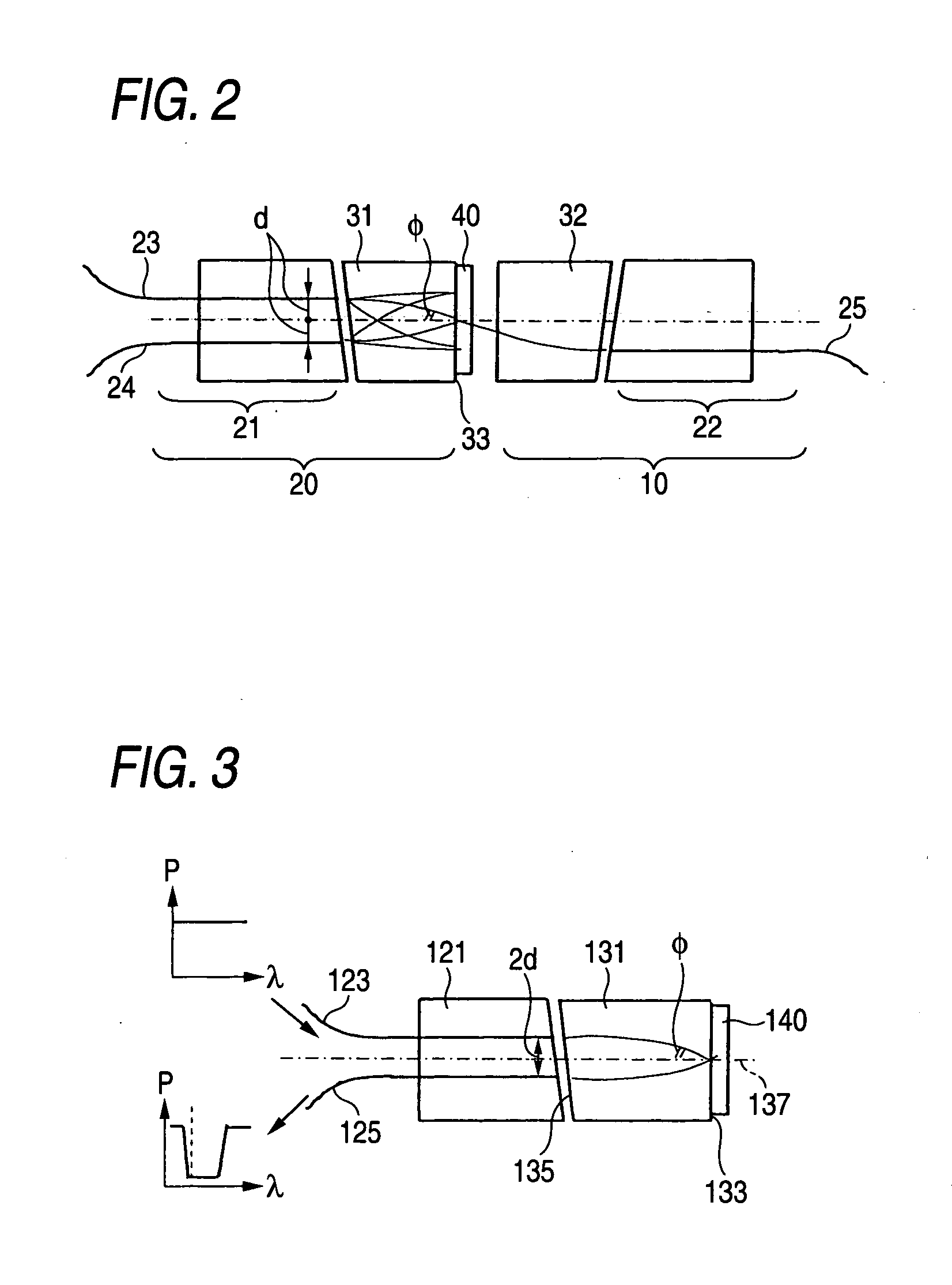
[0061] A dielectric multi-layered BPF having a transmission bandwidth of 0.3 nm was formed on a glass substrate. As illustrated in FIG. 3, a BPF chip (optical filter) 140 is pressed and fixed to an output end 133 of a gradient index rod lens 131 having a refractive index distribution constant √{square root over (A)} of 0.326 mm−1 and a lens length of 0.25 pitches using a jig.

[0062] It is preferable that an input end 135 of the rod lens 131 is inclined to a center axis 137 of the rod lens 131 such that the incident light is prevented...


PUM


Abstract

In a wavelength selective optical device, a lens for transmitting multiplexed optical signals having a plurality of wavelengths is provided to face an end of a first optical fiber such that light output from the end of the first optical fiber is converted into parallel light, and an optical filter is provided at a location to which the parallel light output from the lens is input. A second optical fiber is provided at a location in which the light reflected from the optical filter is input to the lens again to be focused by the lens. The lens is configured by bonding the ends of two gradient index rod lenses having different refractive index distribution constants and the substantially same outer diameter to each other to align their optical axes to each other.

Description

BACKGROUND OF THE INVENTION [0001] 1. Field of the Invention [0002] The present invention relates to a wavelength selective optical device used in a wavelength multiplexing method for superposing optical signals with a plurality of wavelengths and transmitting the optical signals through one optical fiber in an optical communication field. In particular, the present invention relates to a wavelength selective optical device employing an optical filter as a wavelength selecting element and a method of tuning the same. [0003] 2. Related Art [0004] In optical communication field or the like, there are known various devices utilizing the nature of the wavelength of light for controlling transmission and transferring of information. For example, the wavelength division multiplexing large-capacity optical communication (Dense Wavelength Division Multiplexing (DWDM), Coarse Wavelength Division Multiplexing (CWDM), or the like) in which multi-wavelength laser beams with narrow line width ar...

Claims


Application Information

Patent Timeline
Patent Type & Authority Applications(United States)
IPC IPC(8): G02B6/32
CPCG02B6/2937G02B6/32G02B6/29395G02B6/2938
Inventor HASHIZUME, HIDEKITAKEUCHI, KENICHIROLU, HAIGUANG
Owner GOFOTON HLDG
Why Eureka
Try Eureka