Method of manufacturing an end cap of a linear guideway

a manufacturing method and linear technology, applied in the field of manufacturing an end cap of a linear guideway, can solve the problems of increasing the cost of mass production, adversely affecting the function of the linear guideway, and difficult control of the amount of compensation

Inactive Publication Date: 2007-09-13
HIWIN TECH
View PDF2 Cites 0 Cited by
  • Summary
  • Abstract
  • Description
  • Claims
  • Application Information

AI Technical Summary

Benefits of technology

[0008] The primary objective of the present invention is to provide a method of manufacturing an end cap of a linear guideway, which can prevent the end cap from constant deformation during storage.

Problems solved by technology

Therefore, due to stress relief, the end cap 1 will shrink within a certain period of time after mold release and will shrink toward the rail, this will result in an interference of the inner surface of the end cap 1 with the rail, and will cause misalignment of the return paths 121 and other holes, adversely affecting the function of the linear guideway.
However, the plastic deformation is difficult to control because of its elastic recoil property, and this will increase the cost of mass production.
If the deformation is compensated during the course of mold opening, the amount of compensation is difficult to control because the plastic deformation has to do with many factors: including time for mold opening, temperature, material and injection pressure, it will vary with each production.

Method used


Image

  • Method of manufacturing an end cap of a linear guideway
  • Method of manufacturing an end cap of a linear guideway

Examples


Embodiment Construction

[0023] The foregoing, and additional objects, features and advantages of the present invention will become apparent from the following detailed description of preferred embodiments thereof, taken in conjunction with the accompanying drawings.

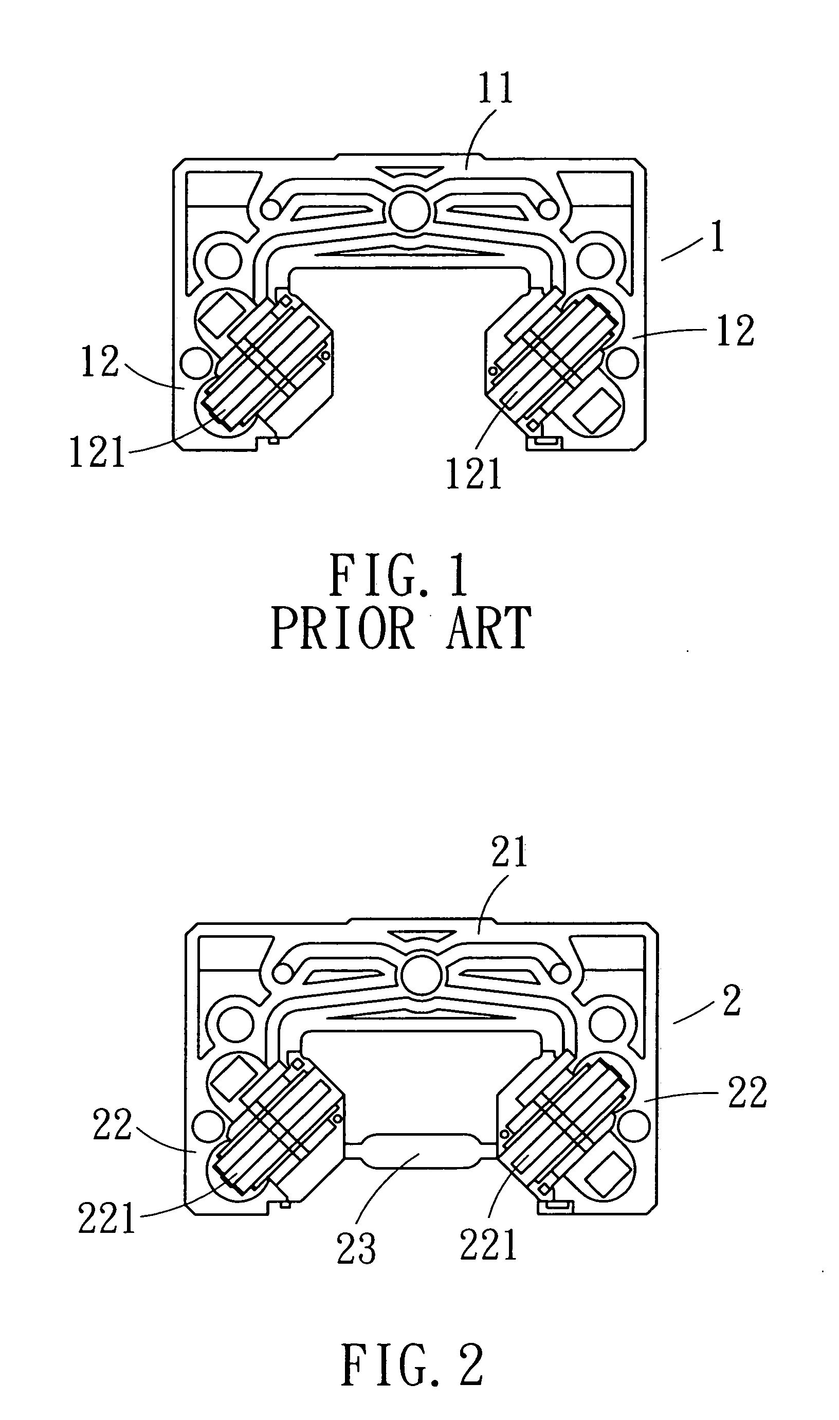
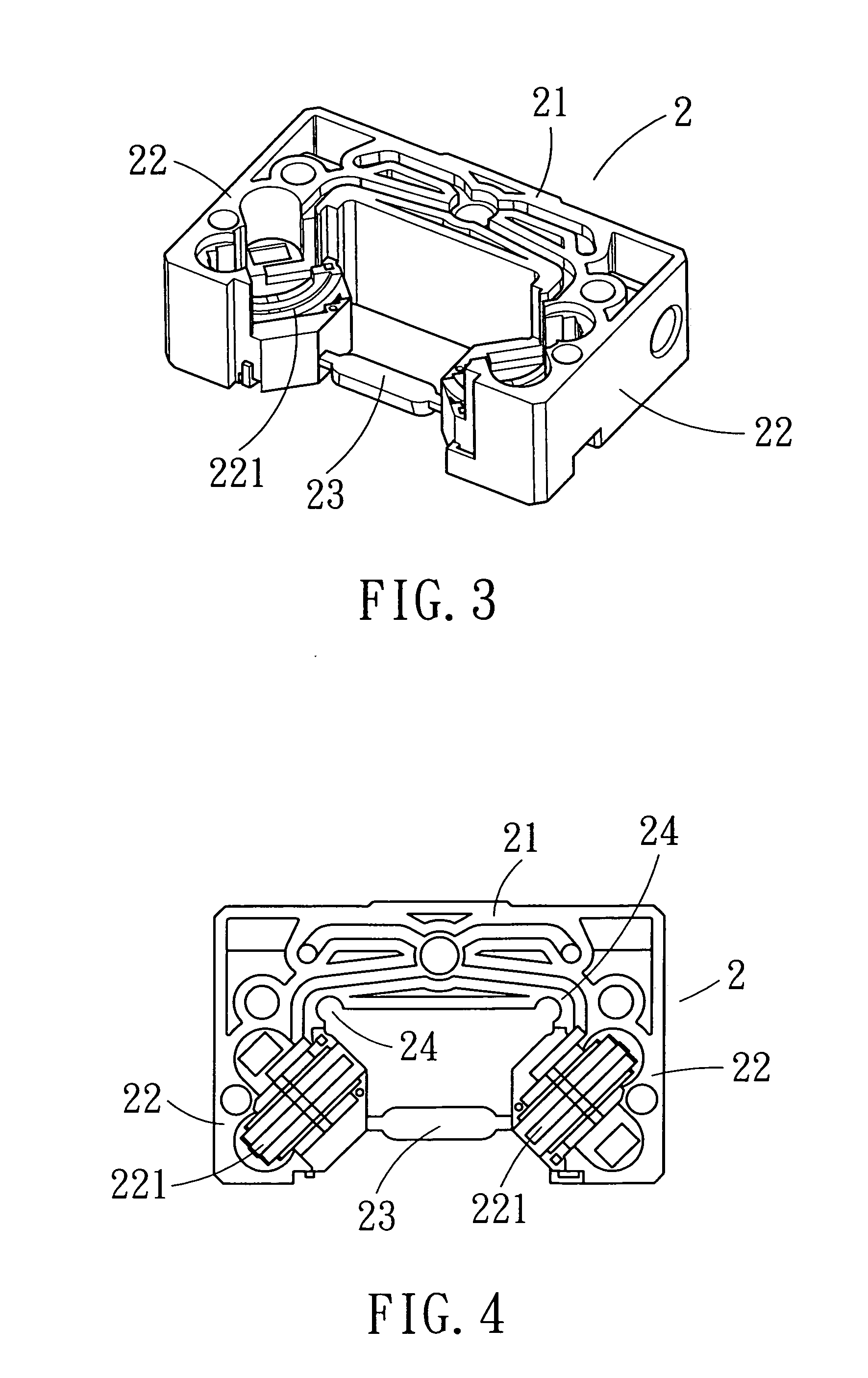
[0024]FIG. 2 is a front view of an intermediate product resulting from a method of manufacturing an end cap of a linear guideway in accordance with the present invention. FIG. 3 is a stereographic of FIG. 2. The finally resultant end cap (the final product) of the present invention is identical with the conventional end cap in outline, and the structure of the intermediate product of the present invention is shown in FIG. 2. The intermediate product shown in FIG. 2 comprises a connecting portion 21 and two side arms 22 at both sides of the connecting portion 21. Each of the side arms 22 is defined with a return path 221. For preventing the occurrence of deformation during the course of mold release, a rib 23 is arranged between the two side arm...


PUM

PropertyMeasurementUnit
strengthaaaaaaaaaa
residual stressaaaaaaaaaa
tensile residual stressaaaaaaaaaa

Abstract

A method of manufacturing an end cap of a linear guideway can keep the finished end cap from constant deformation during storage. The method is to arrange a rib on the intermediate product during the manufacturing process, the rib can be cut away from the intermediate product after stress relief, and thus preventing severe deformation of the intermediate product caused by stress relief.

Description

BACKGROUND OF THE INVENTION [0001] 1. Field of the Invention [0002] The present invention relates to a method of manufacturing an end cap of a linear guideway, and more particularly to a manufacturing method capable of releasing the material's residual stress after injection molding and keeping the end cap from constant deformation during storage. [0003] 1. Description of the Prior Art [0004] A linear guideway essentially comprises a rail and a slide block. The rail is an elongated work piece defined with rolling grooves for enabling the rolling elements to roll therealong, and the slide block is a reverse U-shaped work piece in which is also defined rolling grooves for mating with the rolling grooves of the rail, allowing the rolling elements to roll within the rolling passage defined by the rolling grooves of the slide block and the rail. For enabling the rolling elements to circulate in the linear guideway, the slide block must be provided at both ends thereof with two end caps t...

Claims


Application Information

Patent Timeline
Patent Type & Authority Applications(United States)
IPC IPC(8): B29C45/00
CPCB29C45/0025B29C45/0005
Inventor PAN, PO-LIN
Owner HIWIN TECH
Why Eureka
Try Eureka