Manufacture device and manufacture method for compressor container assembly

A manufacturing method and a manufacturing device technology, which are applied in the field of container assembly manufacturing, can solve problems such as large differences in deformation and achieve a constant trend effect

Active Publication Date: 2016-10-05
MITSUBISHI ELECTRIC CORP
View PDF12 Cites 0 Cited by
  • Summary
  • Abstract
  • Description
  • Claims
  • Application Information

AI Technical Summary

Problems solved by technology

In addition, even if it is the same model, there are individual differences in each compression mechanism
Therefore, there is a problem that the difference in deformation becomes large as the site where the stress is released varies among individuals.

Method used


Image

  • Manufacture device and manufacture method for compressor container assembly
  • Manufacture device and manufacture method for compressor container assembly
  • Manufacture device and manufacture method for compressor container assembly

Examples


Embodiment approach 1

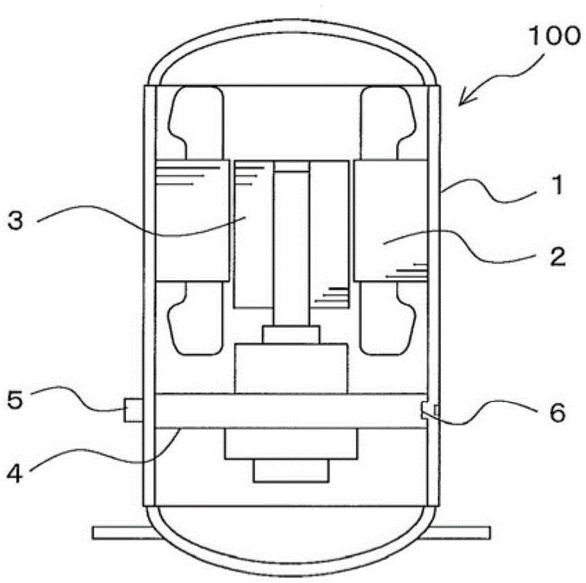
[0056] figure 1 It is a sectional view showing the hermetic compressor 100 according to Embodiment 1 of the present invention.

[0057] Such as figure 1 As shown, in the hermetic compressor 100, the stator 2 is fixed in the hermetic container 1 by shrink fitting. The stator 2 drives the rotor 3 to supply a driving force to a rotating shaft included in the compression mechanism unit 4 . The compression mechanism unit 4 has a suction pipe 5 for supplying compressed refrigerant.

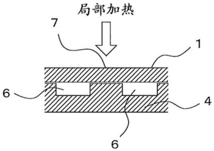
[0058] Here, a method for fixing the compression mechanism unit 4 to the airtight container 1 will be described.

[0059] figure 2 It is a cross-sectional view of main parts for explaining the structure and method of the caulking portion of the hermetic compressor 100 according to Embodiment 1 of the present invention. image 3 It is a cross-sectional view of main parts for explaining the structure and method of the caulking portion of the hermetic compressor 100 according to Embodiment 1 of the p...

Embodiment approach 2

[0122] Next, in Embodiment 2, the manufacturing apparatus which realizes the caulking part formation based on the local heating of the hermetic compressor shown in Embodiment 1 mentioned above is demonstrated.

[0123] Fig. 17 is an overall configuration diagram collectively showing a heat riveting device 21 according to Embodiment 2 of the present invention, Fig. 17(a) is a top view, and Fig. 17(b) is a cross-sectional view taken along line XX in Fig. 17(a) . Figure 18 It is a figure which shows the control part 300 of the heating caulking apparatus 21 concerning Embodiment 2 of this invention. Figure 19 It is a figure which shows the operation flow of the heating caulking apparatus 21 which concerns on Embodiment 2 of this invention.

[0124] Such as Figure 18 As shown, the heat caulking device 21 has a control unit 300 that controls various mechanisms of the heat caulking device 21 . The control unit 300 has a positioning part 300a for the workpiece (compressor to be ...


PUM


Abstract

The purpose of the present invention is to ensure that the locations where stress on an internal component would be released following pressure application on the internal component to fix the same to the inside of a container are made constant so that the deformation tendencies of such internal components are constant. A container assembly manufacturing device according to the present invention is provided with: a heat staking mechanism (24) disposed around the outer circumference direction of an airtight container (1) which houses a compressor mechanism unit (27) that performs a compression operation and comprises at least one upper cylinder (27a) having a plurality of prepared holes (6) formed on the periphery thereof, wherein the heat staking mechanism pushes wall parts of the airtight container (1) that face the plurality of the prepared holes (6) from the outside thereof with pushing jigs (13) having the same or smaller diameters than the prepared holes (6) and forces the wall parts of the airtight container (1) into the prepared holes (6); and a control unit (300) for executing the pushing operation of the heat staking mechanism (24) at predetermined time intervals.

Description

technical field [0001] The present invention relates to an apparatus for manufacturing a compressor container assembly and a method for manufacturing the compressor container assembly, in which components incorporated in compressors used in air conditioners, refrigerators, or water heaters are fixed to an airtight container. Background technique [0002] As a conventional manufacturing method of a compressor, there is a method of drilling a container, shrink-fitting a compression mechanism as a compression unit into the container, flowing molten metal from the outside of the hole, and fixing built-in components such as the compression mechanism container-based method (for example, refer to Patent Document 1). [0003] As a method of fixing the compression mechanism part of a compressor without drilling the container, there is a method of pressing the compression mechanism part of the built-in part into the container and positioning it, and then using a pressing tool to align...

Claims


Application Information

Patent Timeline
Patent Type & Authority Applications(China)
IPC IPC(8): B21D39/00
CPCB21D39/00F04B39/12
Inventor 饭田和树水野隆太郎高桥广康小河雄介
Owner MITSUBISHI ELECTRIC CORP
Why Eureka
Try Eureka