
SLM Lithography: Printing to below K1=.30 without previous OPC processing

a technology of lithography and opc processing, applied in the field of slm lit, can solve the problems of limiting the resolution and fidelity that can be achieved, the optics used in lithographic processes are extremely well designed, and the only limitation is the underlying physics, so as to achieve the effect of size errors for everything close to the resolution limi

Active Publication Date: 2007-09-06
MICRONIC LASER SYST AB
View PDF11 Cites 237 Cited by
  • Summary
  • Abstract
  • Description
  • Claims
  • Application Information

AI Technical Summary

Benefits of technology

[0010] Previously disclosed methods and devices are extended in this application by two-dimensional analysis of optical proximity interactions and by fashioning a computationally efficient kernel for rapid calculation of adjustments to be made. The computations can be made concurrently with rasterizing or even in realtime, whereby the use of OPC assist features can be reduced, with substantial savings in file size and computational requirements. Further aspects of the invention are disclosed in the descriptions, figures, claims and documents incorporated by reference.

Problems solved by technology

Aberrations can be reduced by design, but the influence of diffraction of the light due to its finite wavelength puts a limit to the resolution and fidelity that can be achieved.
Because of the strong economic forces towards smaller and more numerous features on the workpiece, the optics used in lithographic processes are extremely well designed and limited only be the underlying physics, i.e., diffraction.
But for technical purposes, this fall-off means size errors for everything close to the resolution limit and the smallest features that can be printed with good fidelity are far larger than the resolution limit.
The OPC processing can be done using specialized software running on computer farms and still take several hours or even days.
Correcting for the effects of the printing on the wafer adds cost, overhead and lead time.
At the 90 and 65 nm design nodes, pattern data files may be 50 Gbyte or more in size and even the transmission and storage of the files becomes a burden to the design houses and mask shops.
Adding one more layer of OPC corrections for the printing of the mask in an SLM-based pattern generator would add more cost, overhead and make the lead time even longer.

Method used


Image

  • SLM Lithography: Printing to below K1=.30 without previous OPC processing
  • SLM Lithography: Printing to below K1=.30 without previous OPC processing
  • SLM Lithography: Printing to below K1=.30 without previous OPC processing

Examples


Embodiment Construction

[0054] The following detailed description is made with reference to the figures. Preferred embodiments are described to illustrate the present invention, not to limit its scope, which is defined by the claims. Those of ordinary skill in the art will recognize a variety of equivalent variations on the description that follows.

Generic Projection System / Platform

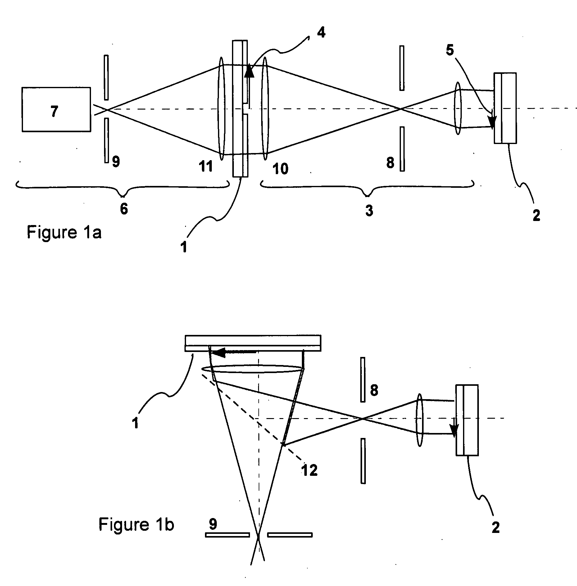
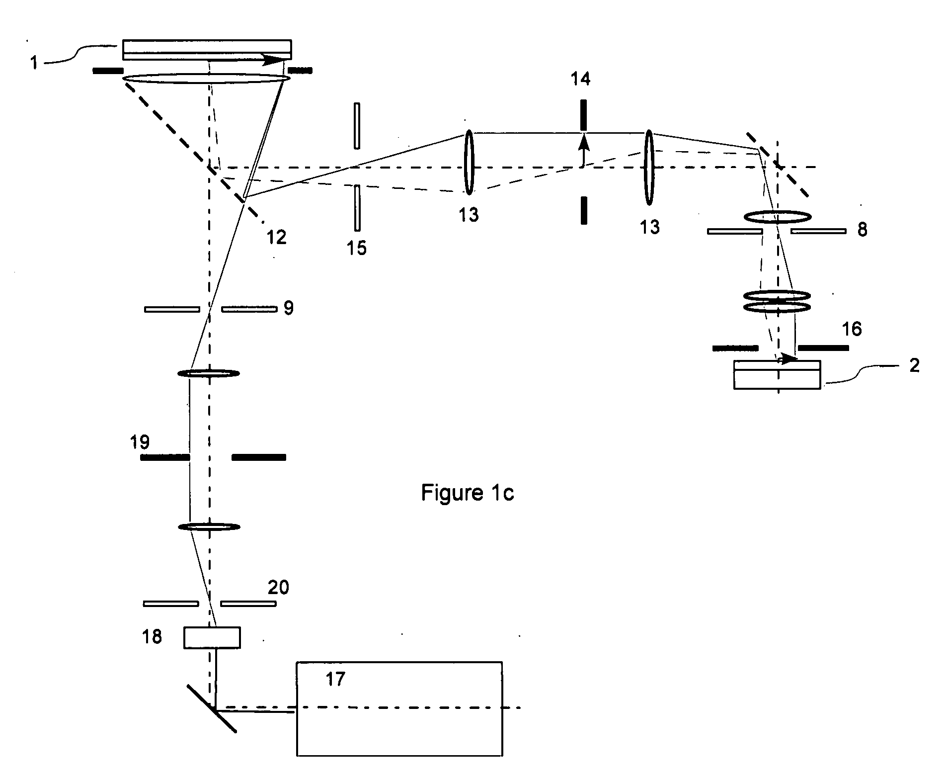
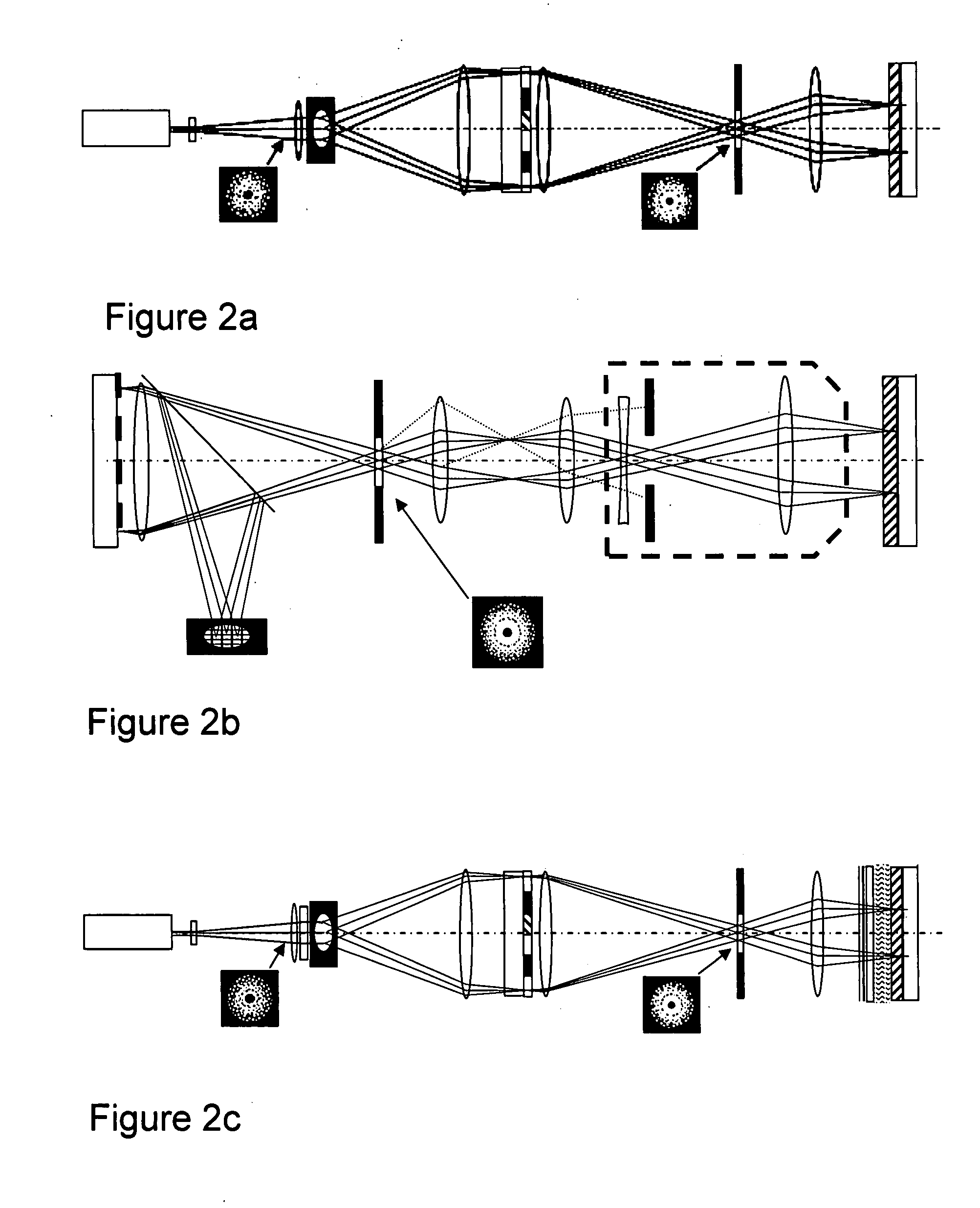
[0055] A generic projection system has been defined in FIG. 1a. It has an object 1, which can be a mask or one or several SLMs, and a workpiece 2, e.g., a mask blank, a wafer or a display device. Between them is a projection system 3 creating an image 5 of the image 4 on the object. The object is illuminated by an illuminator 6. The projection system consists of one or several lenses (shown) or curved mirrors. The NA of the projection system is determined by the size of the pupil 8. The illuminator 6 consists of an essentially non-coherent light source 7 illuminating the illumination aperture 9. Field lenses 10 and 11 are sho...


PUM


Abstract

Previously disclosed methods and devices are extended in this application by two-dimensional analysis of optical proximity interactions and by fashioning a computationally efficient kernel for rapid calculation of adjustments to be made. The computations can be made in realtime, whereby the use of OPC assist features can be reduced, with substantial savings in file size and computational requirements. Further aspects of the invention are disclosed in the descriptions, figures, claims and documents incorporated by reference.

Description

PRIORITY INFORMATION [0001] This application claims the benefit of U.S. Provisional Application No. 60 / 776,275, entitled “SLM Lithography: Printing to Below k1=0.30 Without Previous OPC Processing” filed on 24 Feb. 2006 naming inventors Torbjorn Sandstrom and Igor Ivonin. This application continues in part International Application No. PCT / SE2006 / 000932, entitled “Method and Apparatus for Projection Printing,” filed on 8 Aug. 2006, published in English as WO / 2007 / 018464 and designating the U.S., which International Application claims the benefit of U.S. Provisional Application No. 60 / 706,550, entitled “Method and Apparatus for Projection Printing,” filed on 8 Aug. 2005 naming inventors Igor Ivonin and Torbjorn Sandstrom. The priority documents are hereby incorporated by reference as if set forth in full.FIELD OF THE INVENTION [0002] There are two aspects to the technology disclosed: First, a method and device with a reduced field of interaction, which simplifies and reduces the need...

Claims


Application Information

Patent Timeline
Patent Type & Authority Applications(United States)
IPC IPC(8): G06F17/50
CPCG03F7/70191G03F7/70291G03F7/705G03F7/70441G03F7/70308
Inventor IVONIN, IGORSANDSTROM, TORBJORN
Owner MICRONIC LASER SYST AB
Learn More