Abnormality detection system and method of detecting abnormality

a detection system and abnormality technology, applied in the field of abnormality detection system and method of detection, can solve the problems of constant alarms, inability to detect abnormalities, so as to effectively detect abnormalities in control characteristics, suppress the occurrence of type-1 errors, and effectively detect abnormalities in control

Active Publication Date: 2007-08-30
RENESAS ELECTRONICS CORP +1
View PDF28 Cites 10 Cited by
  • Summary
  • Abstract
  • Description
  • Claims
  • Application Information

AI Technical Summary

Benefits of technology

[0036]Since this example represents the control of the number of micro-defects, the detection sensitivity should be increased with respect to the case of exceeding the upper limit (Ref. FIG. 6) and the case where the value increases (Ref. FIGS. 8 and 10). In other words, when performing the specification control it is of primary importance to determine the upper control limit, so as to issue the alarm when the limit is exceeded or approached. Such arrangement enables minimizing the alarms originating from the type-1 error and issuing only the alarms that are really necessary. Specifically, the rule relevant to FIG. 6, FIG. 8 or FIG. 10 is to be primarily applied. When applying the rule relevant to FIG. 10, the CL is set at zero. In this case, the rules relevant to FIGS. 7, 9, 12 and 13 cannot be applied since those rules require setting the CL. Setting the CL at zero in the rule relevant to FIG. 7 as in the rule relevant to FIG. 10 results in the problem that the alarm keeps being issued after the ninth plot.
[0055]In the abnormality detection system and method of detecting the abnormality thus arranged, the abnormality is decided to exist when generally the same control characteristic values are detected (m+1) consecutive times. Such arrangement allows suppressing occurrence of the type-1 error and effectively detecting the abnormality in control characteristic values originating from the malfunction of the measurement system or communication system.
[0056]Thus, the present invention provides an abnormality detection system and a method of detecting abnormality that allow suppressing occurrence of a type-1 error and effectively detecting the abnormality in control characteristic values originating from a malfunction of a measurement system or a communication system.

Problems solved by technology

However, while the automation has been achieved in all of the data acquisition, calculation, graph drawing and abnormality decision, it has now been discovered that characteristic abnormalities exist that cannot be decided as abnormal by the conventional abnormality decision method, or that can only be detected through numerous type-1 errors.
However, when something goes wrong in a reading system of the laser scattered beam in the inspection equipment, in a data calculation system, or in the communication system, the measurement value may become “zero”.
Setting the CL at zero in the rule relevant to FIG. 7 as in the rule relevant to FIG. 10 results in the problem that the alarm keeps being issued after the ninth plot.

Method used


Image

  • Abnormality detection system and method of detecting abnormality
  • Abnormality detection system and method of detecting abnormality
  • Abnormality detection system and method of detecting abnormality

Examples


Embodiment Construction

[0075]The invention will be now described herein with reference to illustrative embodiments. Those skilled in the art will recognize that many alternative embodiments can be accomplished using the teachings of the present invention and that the invention is not limited to the embodiments illustrated for explanatory purposes.

[0076]Hereunder, an exemplary embodiment of an abnormality detection system and a method of detecting abnormality according to the present invention will be described in details, referring to the accompanying drawings. In the drawings, same constituents are given the same numerals, and the description thereof will not be repeated.

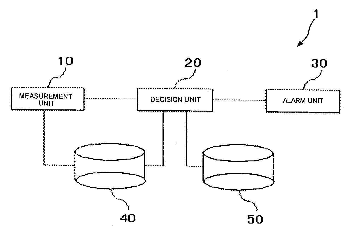
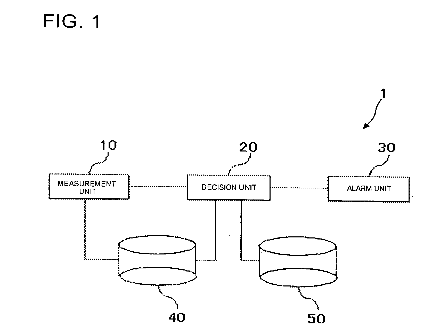
[0077]FIG. 1 is a block diagram of the abnormality detection system according to an embodiment of the present invention. The abnormality detection system 1 includes a measurement unit 10, a decision unit 20, an alarm unit 30, and storage units 40, 50, and serves to detect the abnormality in a control characteristic value of a plurality o...


PUM


Abstract

An abnormality detection system includes a measurement unit, a decision unit, an alarm unit, and storage units, and serves to detect the abnormality in a control characteristic value of a plurality of products manufactured on the same production line. The decision unit receives the control characteristic value stored in the storage unit, and decides whether an abnormality exists, based on that value. More specifically, the decision unit decides that the control characteristic value is abnormal when, with respect to m (m is a natural number) pieces of the products that are consecutively manufactured, an absolute value of a difference in control characteristic value between each of the products and another manufactured immediately before the former is equal to or less than a predetermined constant.

Description

[0001]This application is based on Japanese patent application No. 2006-007403, the content of which is incorporated hereinto by reference.BACKGROUND[0002]1. Technical Field[0003]The present invention relates to an abnormality detection system that detects abnormality in control characteristic values of a plurality of products manufactured on the same production line, and to a method of detecting the abnormality.[0004]2. Related Art[0005]Administration process based on control charts currently in practice has been established on the premise of employing data acquired through measurement, calculating averages and ranges by hand, and marking plots on graphs. Thus, various contrivances that can eliminate the need to use a calculator are incorporated in the process.[0006]Japanese Laid-open patent publication No.H05-333834 (patent document 1) discloses a control chart display apparatus that distinctly displays on the same screen a plurality of abnormal points in the control chart. The ex...

Claims


Application Information

Patent Timeline
Patent Type & Authority Applications(United States)
IPC IPC(8): G06F19/00G05B19/418
CPCG05B23/024G05B2219/1112G05B2219/11G05B2223/02Y02P90/02
Inventor HIGASHIDE, MASANOBUSADAKUNI, GOUKI
Owner RENESAS ELECTRONICS CORP
Why Eureka
Try Eureka