
Induced flow fan with outlet flow measurement

a technology of flow fan and outlet flow, which is applied in the direction of ventilation system, heating type, lighting and heating apparatus, etc., can solve the problems that the test facility required to measure outlet flow by the fan manufacturer cannot be used to measure system performance, and the technology is generally inaccurate, so as to achieve accurate measurement and monitoring of output flow, not to significantly disturb the outlet flow

Inactive Publication Date: 2007-08-30
GREENHECK FAN
View PDF14 Cites 21 Cited by
  • Summary
  • Abstract
  • Description
  • Claims
  • Application Information

AI Technical Summary

Benefits of technology

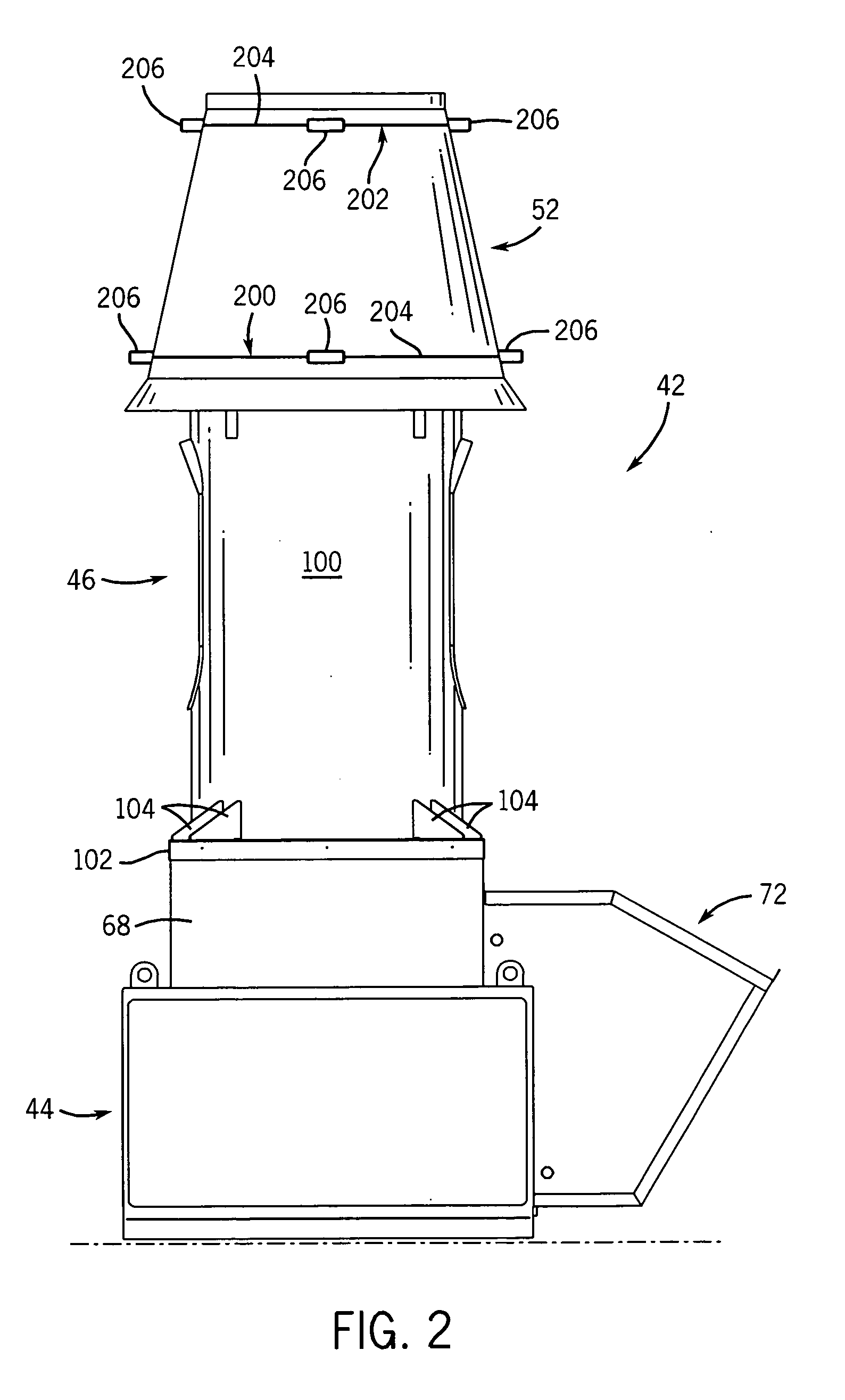
[0012] Multiple pressure taps can form one or more piezometer rings, preferably one ring being mounted at the interior of each end of the windband. The taps at each end can be spaced apart angularly to form the rings, for example three or more pressure taps can be used, and more particularly four pressure taps can be located at the 3, 6, 9 and 12 o'clock positions. The use of multiple taps at each axial position prevents the measurement system from being rendered inoperable from a blocked or damaged tap, and corrects for uneven pressure differential at different locations angular positions around the windband.

Problems solved by technology

This technique is generally inaccurate due to the complicated velocity profiles that are characteristic of induced flow fans, and because the physical presence of the measuring device will interfere with the flow of the expelled air being measured.
This technique may also subject a human technician to the potentially harmful fumes and contaminants in the expelled air.
The large, complex test facilities required to measure outlet flow by the fan manufacturer cannot be used to measure system performance once an exhaust system is installed in a building.

Method used


Image

  • Induced flow fan with outlet flow measurement
  • Induced flow fan with outlet flow measurement
  • Induced flow fan with outlet flow measurement

Examples


Embodiment Construction

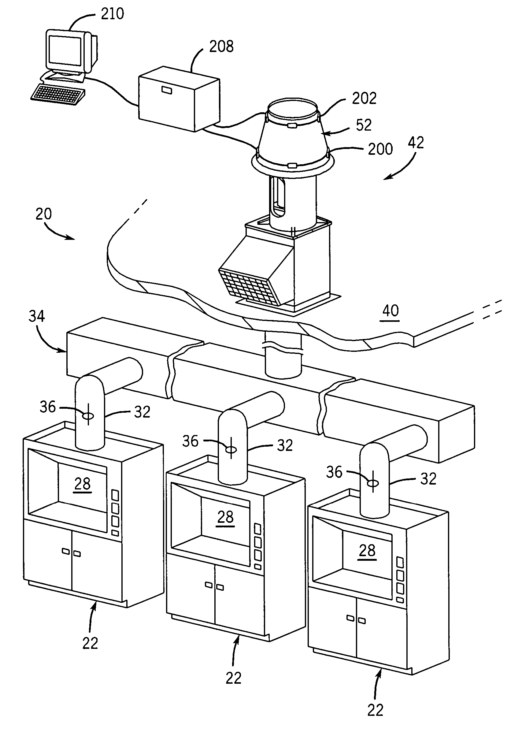
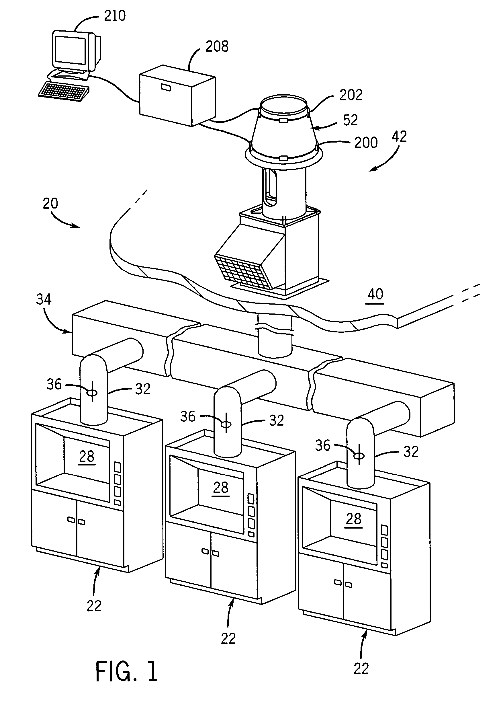
[0024] Referring to FIG. 1, a building ventilation system 20 includes one or more fume hoods 22 of the type commonly installed in commercial kitchens, laboratories, manufacturing facilities, or other appropriate locations throughout a building that create noxious or other gasses that are to be vented from the building. In particular, each fume hood 22 defines a chamber 28 that is open at a front of the hood for receiving surrounding air. The upper end of chamber 28 is linked to the lower end of a conduit 32 that extends upwardly from the hood 22 to a manifold 34. Manifold 34 is further connected to a riser 38 that extends upward to a roof 40 or other upper surface of the building. The upper end of riser 38 is, in turn, connected to an exhaust fan assembly 42 that is mounted on top of roof 40 and extends upwardly away from the roof for venting gasses from the building. The components of exhaust fan assembly 42 are made of a metal, and preferably steel, unless described otherwise here...


PUM


Abstract

An induced flow fan assembly is provided with a pressure tap arrangement at the outlet for measuring the output flow of the assembly. The pressure sensing arrangement includes two rings of piezometers mounted to an outlet windband, one ring at the wider upstream end of the wind band and the outer at the narrower downstream end. Data regarding the pressure differential across the windband is acquired electronically and used to determine total output flow of inlet and entrained air streams. The fan assembly is suitable as an exhaust assembly for expelling contaminated air from a building.

Description

CROSS-REFERENCE TO RELATED APPLICATIONS [0001] Not applicable. STATEMENT OF FEDERALLY SPONSORED RESEARCH / DEVELOPMENT [0002] Not applicable. BACKGROUND OF THE INVENTION [0003] The present invention relates generally to induced flow fans of the type having greater outlet flow than inlet flow, and more particularly to the measurement of outlet flow of such fans. [0004] One example of an application where induced flow fans are commonly used is in building exhaust systems for buildings such as laboratories that produce fumes from chemical and biological processes that may be malodorous, noxious or toxic. The exhaust systems draw contaminated air from the building, mix the contaminated air with ambient air to dilute the contaminants, and vent the diluted air from the building into the ambient environment. Exhaust systems have been devised to expel the mixed air in a plume at a high velocity high above the building so that ground air is not affected by the exhaust. Examples of such systems...

Claims


Application Information

Patent Timeline
IPC IPC(8): B60H1/34
CPCB08B15/002F24F7/025F04D27/001F05D2270/3015F05D2270/301F04F5/54
Inventor SELIGER, MICHAEL G.KURSZEWSKI, SCOTT S.
Owner GREENHECK FAN
Learn More