Reducing abrasive wear in wear resistant coatings

Active Publication Date: 2007-08-30
SCHLUMBERGER TECH CORP
View PDF3 Cites 20 Cited by
  • Summary
  • Abstract
  • Description
  • Claims
  • Application Information

AI Technical Summary

Benefits of technology

[0008] Aspects and embodiments of the present invention are directed to the reduction of the wear rate exhibited by a wear surface used within an abrasive environment. In one embodiment, an abrasive resistant coating for use within an abrasive environment is provided. To reduce the wear exhibited by this abrasive resistant coating, the area of exposed ductile material is minimized, such that harder brittle components are in contact with the abrasive environment. Brittle components such as these, as compared to the softer ductile components, provide increase service life and reduced wear of the abrasive resistant coating, as compared to contact of the softer ductile material with an abrasive environment.
[0010] Minimization of the interparticle spacing of the present embodiment may take numerous forms, including the use of a bimodal size distribution of brittle components having a primary brittle component size as well as brittle components having an interstitial brittle component size. The interstitial brittle components are typically smaller in size than the primary brittle components such that the exposed area of the ductile metal Matrix is minimized. Using a bimodal distribution of brittle components such as this allows for an interparticle spacing of brittle components less than 5 microns. Additionally, the brittle component, both primary and interstitial, may exhibit a spherical morphology to aid in reduction of contact stress between the brittle components and the abrasive environment. An applicable abrasive environment is a borehole of a oil, water, or gas well, for example.
[0012] In accordance with an alternate embodiment, a method for reducing the wear rate of an abrasive resistant coating in contact with an abrasive environment is provided. This method includes the steps of first providing a suitable substrate for application of the abrasive resistant coating. One such suitable substrate is a metallic tool element, such as a wear pad of a direction drilling apparatus. Applied to the substrate is a matrix wear surface, wherein the matrix wear surface has both brittle and ductile components. As these components are in contact with an abrasive environment, such as a borehole for example, the rate of wear is reduced if the exposure of the soft, ductile material in contact with the abrasive environment is minimized. Minimization of the exposed ductile material may be accomplished by selecting an interstitial particle size which results in roughly closed packed brittle components with a primary size. These roughly closed pack brittle components are situated such that the ductile material exposed to the environment is minimized, thereby resulting in decreased wear.

Problems solved by technology

Application of the wear surface to the substrate may be uniform in applied thickness, or may be non-uniform in applied thickness.
A non-uniform application of the wear surface provides for the increased thickness of the wear surface in areas that exhibit the greatest wear.

Method used


Image

  • Reducing abrasive wear in wear resistant coatings
  • Reducing abrasive wear in wear resistant coatings
  • Reducing abrasive wear in wear resistant coatings

Examples


Embodiment Construction

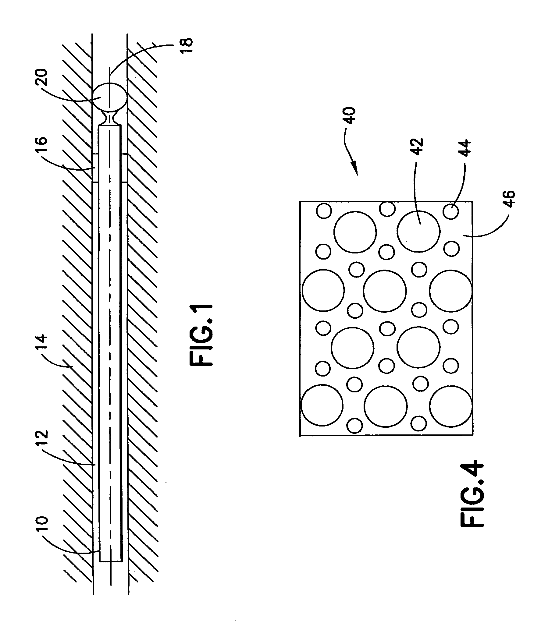
[0023] Various embodiments and aspects of the invention will now be described in detail with reference to the accompanying figures. This invention is not limited in its application to the details of construction and the arrangement of components set forth in the following description or illustrated in the drawings. The invention is capable of various alternative embodiments and may be practiced using a variety of other ways. Furthermore, the terminology and phraseology used herein is solely used for descriptive purposes and should not be construed as limiting in scope. Language such as “including,”“comprising,”“having,”“containing,” or “involving,” and variations herein, are intended to encompass the items listed thereafter, equivalents, and additional items not recited. Furthermore, the terms “hardface surface”, “wear surface”, “matrix wear surface”, “abrasive resistant coating”, “abrasion resistant surface” and variations herein will be used interchangeable to describe the present...


PUM

PropertyMeasurementUnit
Lengthaaaaaaaaaa
Lengthaaaaaaaaaa
Sizeaaaaaaaaaa

Abstract

An abrasion resistant coating and method are provided wherein the abrasion resistant coating contains both ductile and brittle components having a bimodal size distribution. The abrasion resistant coating is initially applied to a substrate in contact with an abrasive environment. The abrasive resistant coating having a bimodal size distribution results in the minimized exposure of the ductile components of the wear surface to the abrasive environment such that the life of the abrasive resistant coating is extended.

Description

FIELD OF THE INVENTION [0001] The present invention relates to a method of improving the abrasive wear of hard-coatings, and more particularly to hard-coatings having a distribution of reinforcement throughout its microstructure. BACKGROUND OF THE INVENTION [0002] The surfaces of downhole tools, when in contact with an abrasive environment such as a borehole wall, can undergo a high level of abrasion. In light of this, these surfaces are oftentimes coated with an abrasive resistant coating, in an effort to reduce wear and extend tool life. For example, abrasive resistant coatings, or hard facings, are often applied to susceptible areas of a tool such as wear bands, directional drilling pressure pads and stabilizers. Coatings such as these are typically a particulate metal matrix composite, based on a nickel or cobalt alloyed matrix containing tungsten or titanium carbides particles. Using such a combination, both high degrees of hardness and toughness can be obtained. [0003] These c...

Claims


Application Information

Patent Timeline
IPC IPC(8): B32B15/04
CPCC23C4/06C23C30/00Y10T428/252Y10T428/12951Y10T428/12576
Inventor HUMPHREYS, ALAN O.GANGULY, PARTHAPAFITIS, DEMOSTHENIS
Owner SCHLUMBERGER TECH CORP
Why Eureka
Try Eureka