
Compliant electroactive polymer transducers for sonic applications

Inactive Publication Date: 2007-08-30
SRI INTERNATIONAL
View PDF24 Cites 97 Cited by
  • Summary
  • Abstract
  • Description
  • Claims
  • Application Information

AI Technical Summary

Benefits of technology

[0011] In one aspect, the present invention relates to a sonic device. The sonic device includes an electroactive polymer transducer and a circuit. The electroactive polymer transducer includes a portion of an electroactive polymer and a first electrode in contact with the portion and a second electrode in contact with the portion. The electroactive polymer transducer is arranged in a manner which causes the portion to deflect in response to a change in electric field that is applied via at least one of the first electrode and the second electrode. The electroactive polymer has an elastic modulus less than about 100 MPa. The circuit in electrical communication with the first electrode and the second electrode and configured to provide an actuation signal to at least one of the first electrode and second electrode. The actuation signal causes the electroactive polymer transducer to deflect at a frequency less than about 50 kHz.
[0012] In another aspect, the present invention relates to a method of producing sound. The method includes providing an electroactive polymer transducer. The transducer has an electroactive polymer and a first electrode in contact with a first surface of the electroactive polymer and a second electrode in contact with a

Problems solved by technology

Accordingly, for applications requiring high spatial resolution but with weight and space limitations, such as in automotive and aerospace applications, electromagnetic acoustic actuators are impractical.
The movable plate is electrostatically attracted to the stationary plate While electrostatic speakers are lightweight and can be made to have a relatively low profile, they have several disadvantages for many applications.
These speakers tend to be costly since it is necessary to carefully construct the speaker so that the moving plate does not contact the stationary plate, but with a small enough air gap so that the driving voltage is not required to be excessive.
Additionally, because the radiating plate must maintain a nearly constant spacing from a rigid stationary plate, these speakers are limited to flat-mounted applications.
Further, as electrostatic speakers typically operate with a bias voltage of several thousand volts, limitations on the driving voltage will also limit the acoustic power output.

Method used


Image

  • Compliant electroactive polymer transducers for sonic applications
  • Compliant electroactive polymer transducers for sonic applications
  • Compliant electroactive polymer transducers for sonic applications

Examples


Embodiment Construction

[0030] Before describing particular embodiments of the sonic devices, systems and applications, a discussion of compliant electroactive polymer transducers and their material properties and performance characteristics is provided, followed by a description of several suitable electroactive polymer actuators.

Electroactive Polymer Transducers

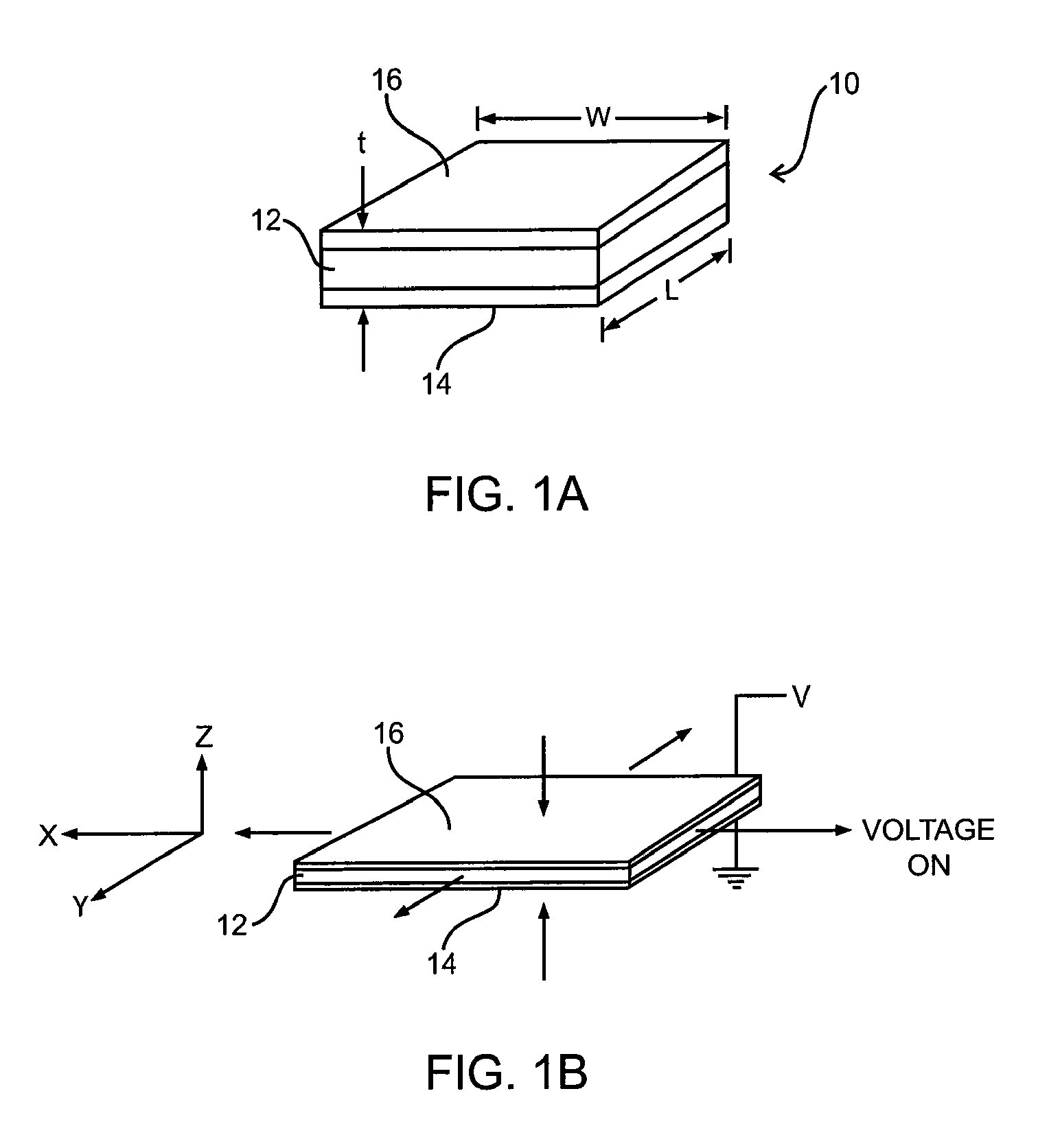
[0031]FIGS. 1A and 1B illustrate an electroactive polymer transducer 10, the basic functional element of the present invention. A portion of thin elastomeric polymer 12, also commonly referred to as a film or membrane, is sandwiched between compliant electrodes 14 and 16. In this elastomeric polymer transducer, the elastic modulus of the electrodes is generally less than that of the polymer, and the length “L” and width “W” of the film are much greater than the thickness “t”.

[0032] As seen in FIG. 1B, when a voltage is applied across the electrodes, the unlike charges in the two electrodes 14, 16 are attracted to each other and these electrosta...


PUM


Abstract

Described herein are compliant electroactive polymer transducers for use in acoustic applications. A compliant electroactive polymer transducer includes a compliant electroactive polymer at least two electrodes. For sound production, circuitry in electrical communication with the transducer electrodes is configured to apply a driving signal that causes the electroactive polymer to deflect in the acoustic range.

Description

CROSS-REFERENCE TO RELATED APPLICATIONS [0001] This application claims priority under 35 U.S.C. §119(e) from U.S. Provisional Patent Application No. 60 / 776,265 filed Feb. 24, 2006, naming Roy Kornbluh et al. as inventors, and titled “Compliant Polymer Usage in Sonic Applications”; this application also claims priority under U.S.C. §120 and is continuation-in-part of co-pending U.S. patent application No. 11 / 335,805, filed Jan. 18, 2006 and entitled, “ELECTROACTIVE POLYMERS”, which is incorporated herein for all purposes; this '805 patent application claimed priority under U.S.C. §120 from U.S. Pat. No. 7,049,732, filed Jul. 16, 2004 and entitled, “ELECTROACTIVE POLYMERS” (and co-pending at filing of '983); this '732 patent claimed priority from U.S. Pat. No. 6,812,624 (which was co-pending at filing of '732); '624 claimed priority under 35 U.S.C. §119(e) from a) U.S. Provisional Patent Application No. 60 / 144,556 filed Jul. 20, 1999, naming R. E. Pelrine et al. as inventors, and titl...

Claims


Application Information

Patent Timeline
IPC IPC(8): H01L41/00
CPCH04R19/02Y10S310/80
Inventor HEYDT, RICHARD P.PELRINE, RONALD E.KORNBLUH, ROY D.BONWIT, NEVILLE A.ECKERLE, JOSEPH S.
Owner SRI INTERNATIONAL
Learn More