Apparatus and method for identification of optical cable

a technology of optical cable identification and optical cable, applied in the field of optical cable identification apparatus, to achieve the effect of precise identification of optical cabl

Inactive Publication Date: 2007-08-23
KT CORP
View PDF2 Cites 21 Cited by
  • Summary
  • Abstract
  • Description
  • Claims
  • Application Information

AI Technical Summary

Benefits of technology

[0010] The present invention has been made in an effort to provide an optical cable identification apparatus that can

Problems solved by technology

In this case, there is a possibility of cutting a cable path in a communication state when a wrong cable is selected.
However, there is a problem in application o

Method used


Image

  • Apparatus and method for identification of optical cable
  • Apparatus and method for identification of optical cable
  • Apparatus and method for identification of optical cable

Examples


Embodiment Construction

[0030] In the following detailed description, only certain exemplary embodiments of the present invention have been shown and described, simply by way of illustration. As those skilled in the art would realize, the described embodiments may be modified in various different ways, all without departing from the spirit or scope of the present invention. Accordingly, the drawings and description are to be regarded as illustrative in nature and not restrictive. Like reference numerals designate like elements throughout the specification.

[0031] In addition, throughout this specification and the claims which follow, unless explicitly described to the contrary, the word “comprise” and variations such as “comprises” or “comprising” will be understood to imply the inclusion of stated elements but not the exclusion of any other elements.

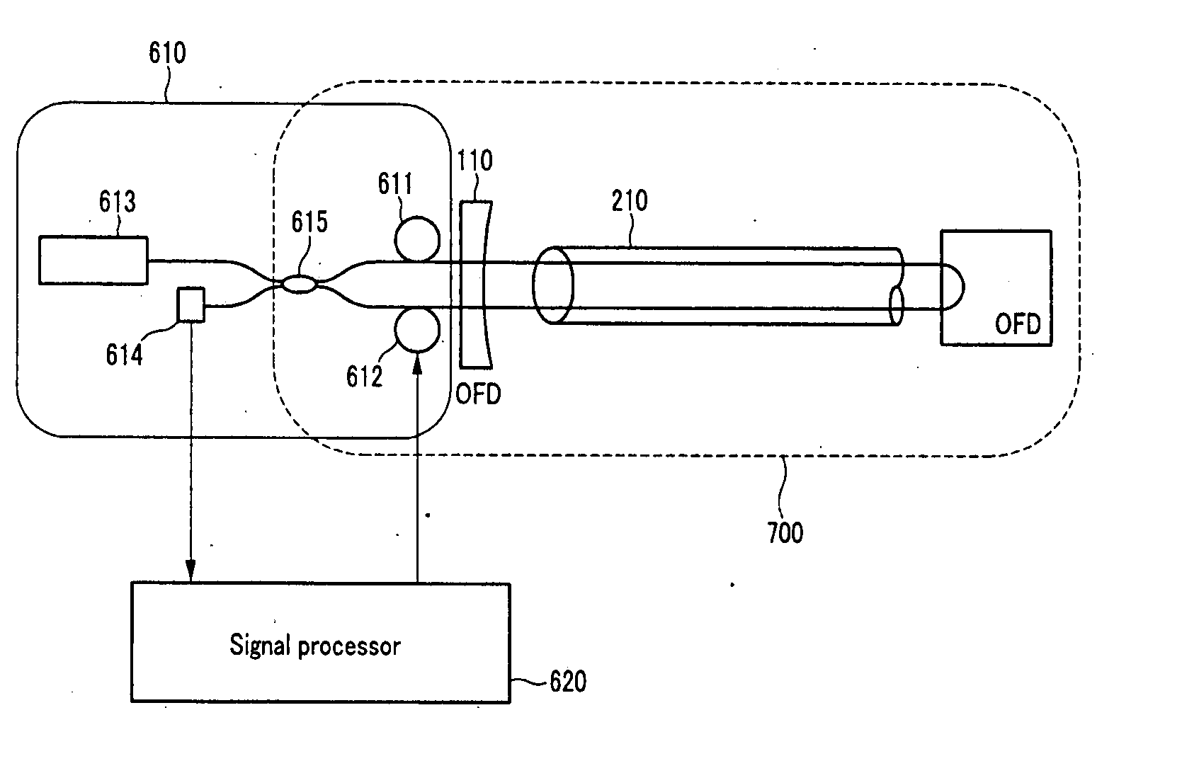
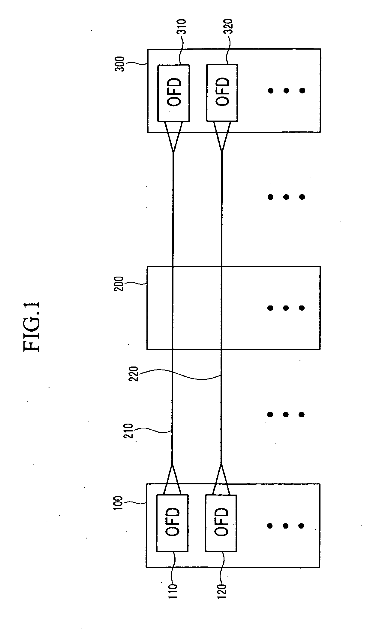
[0032]FIG. 1 shows a connection relationship of optical cables to be applied to the present invention.

[0033] Referring to FIG. 1, a plurality of optical cab...


PUM


Abstract

In order to identify an optical cable for optical communication from a remote place, a Sagnac interferometer including two strands of an optical fiber is formed in the optical cable, and a worker in the remote place applies a disturbance of a popping sound to an optical cable to be identified. The disturbance applied by the worker is detected and regenerated in the form of a sound. The optical cable can be easily identified by comparing the regenerated signal and the disturbed signal in the remote place to thereby prevent an incorrect optical cable from being cut. In addition, the optical cable can be more precisely identified by selecting a different light detecting frequency component in accordance with environment conditions.

Description

CROSS-REFERENCE TO RELATED APPLICATION [0001] This application claims priority to and the benefits of Korean Patent Application Nos. 10-2005-0077441 and 10-2006-0078111 respectively filed in the Korean Intellectual Property Office on Aug. 23, 2005 and Aug. 18, 2006, the entire contents of which are incorporated herein by reference. BACKGROUND OF THE INVENTION [0002] (a) Field of the Invention [0003] The present invention relates to an optical cable identification apparatus. More particularly, the present invention relates to a method for identifying an optical cable in a remote place, and an apparatus using the same. Herein, the remote place refers to a place (e.g., a manhole) remote from a central office where communication equipment is located. [0004] (b) Description of the Related Art [0005] In general, a phone line or other communication line is connected between one central office to another central office, and a plurality of manholes are provided between the central offices fo...

Claims


Application Information

Patent Timeline
IPC IPC(8): G02B6/44H04B10/00H04B10/079
CPCH04B10/07953G01M11/3172
Inventor LEE, YONG-GIYOUN, KYEONG-MOJEONG, HYUN-HOMIN, KYOUNG-SEONJEONG, HO-JINLEE, BONG-WAN
Owner KT CORP
Why Eureka
Try Eureka