
Time-interleaved analog-to-digital converter having timing calibration

Inactive Publication Date: 2007-08-23
NATIONAL CHIAO TUNG UNIVERSITY
View PDF7 Cites 19 Cited by
  • Summary
  • Abstract
  • Description
  • Claims
  • Application Information

AI Technical Summary

Benefits of technology

[0007] The main purpose of the present invention is to dynamically calibrate timing of both narrow-band signals and wid

Problems solved by technology

But, because timing skew will slightly changes with the temperature and the outside environment on running the circuit, a main disadvantage of this method is that a dynamic calibration of timing-skew error is not available and the converter becomes inferior after a period of operation.
But this method can only be applied in a narrow-bandwidth operation.
When the bandwidth of the input signal is wider than a half of the sampling frequency of a single channel, signal aliasing appears and fails this method.
Although the above methods processes timing-skew calibrations, the foreground calibration method is not able to process a calibration dynamically and the correction of cross-correlation function test can be applied to narrowband signals only.
Hence, the prior arts do not fulfill users' requests on actual use.

Method used


Image

  • Time-interleaved analog-to-digital converter having timing calibration
  • Time-interleaved analog-to-digital converter having timing calibration
  • Time-interleaved analog-to-digital converter having timing calibration

Examples


first embodiment

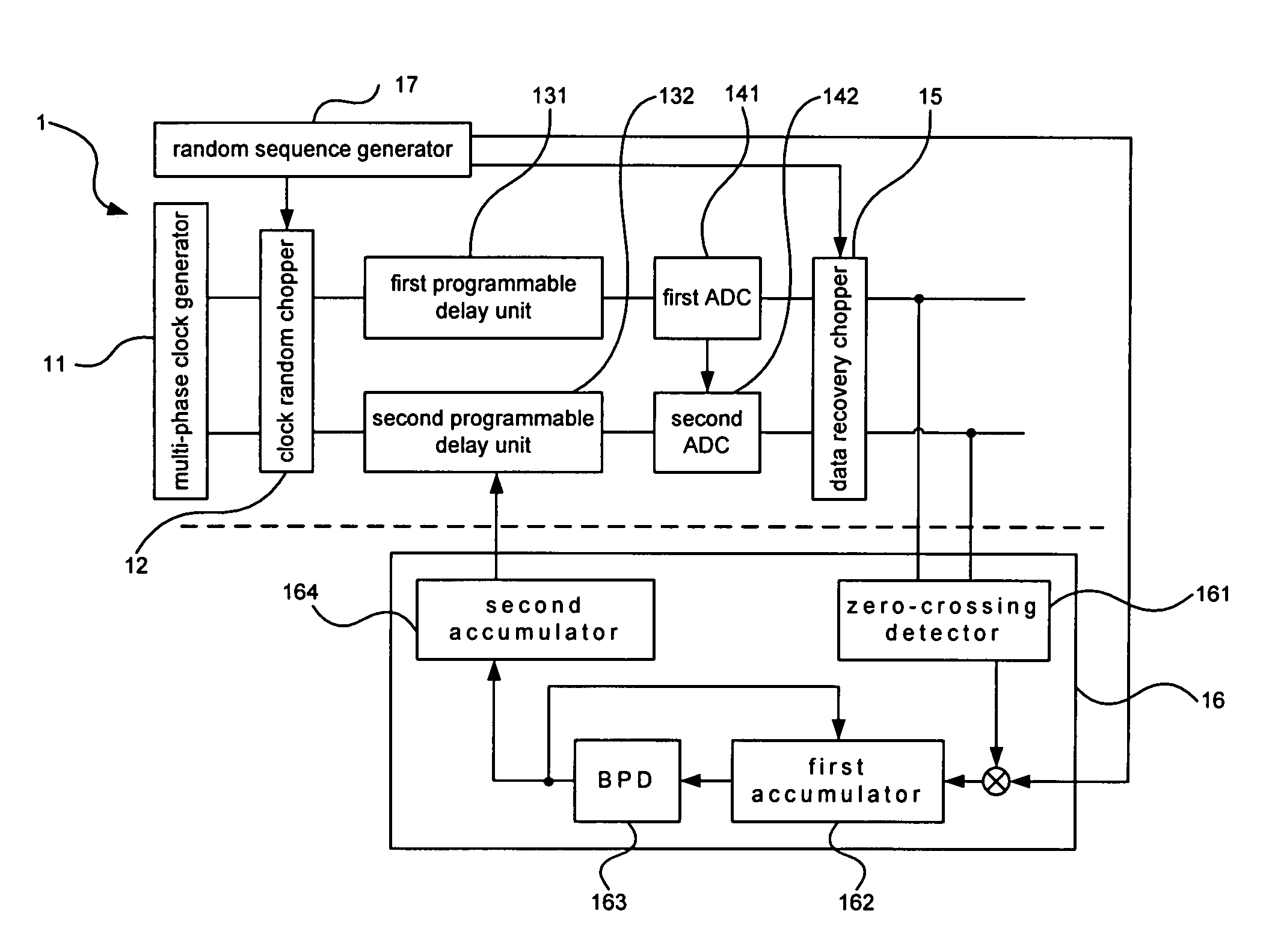
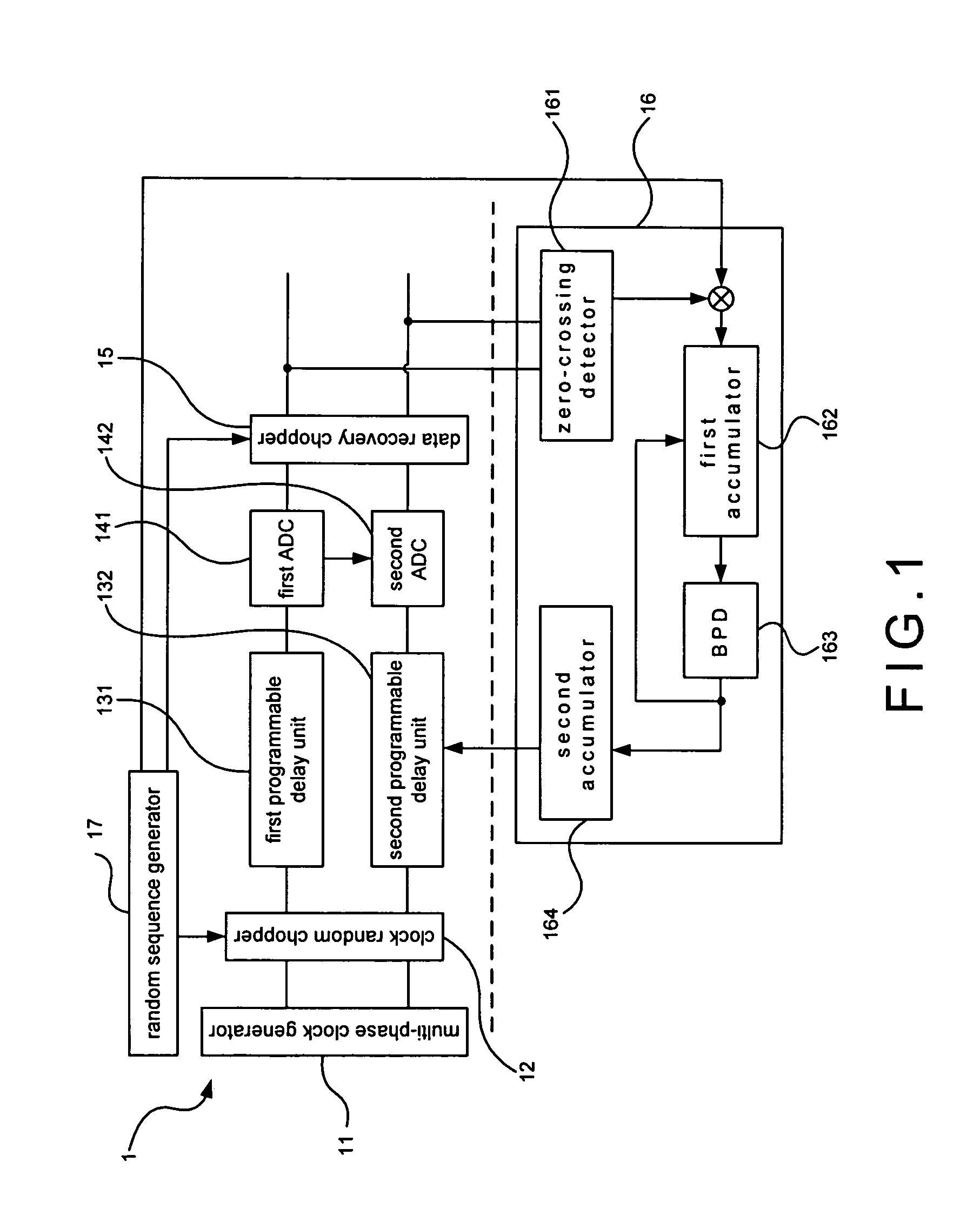
[0013] Please refer to FIG. 1, which is a structural view showing a first preferred embodiment according to the present invention. As shown in the figure, the present invention is a time-interleaved analog-to-digital converter (ADC) having a timing calibration. The first embodiment is a two-channel background calibrated time-interleaved ADC 1, comprising a multi-phase clock generator 11, a clock random chopper 12, a first programmable delay unit 131, a second programmable delay unit 132, a first ADC 141, a second ADC 142, a data recovery chopper 15, a calibration processor 16 (CP) and a random sequence generator 17.

[0014] Therein, the CP 16 comprises a zero-crossing detector 161, a first accumulator 162, a bilateral peak detector (BPD) 163 and a second accumulator 164. The first accumulator 162 can be a flexible-symbol accumulator; or, the first accumulator 162 and the second accumulator 164 can be replaced with a counter.

[0015] When using the first preferred embodiment, the multi-...

second embodiment

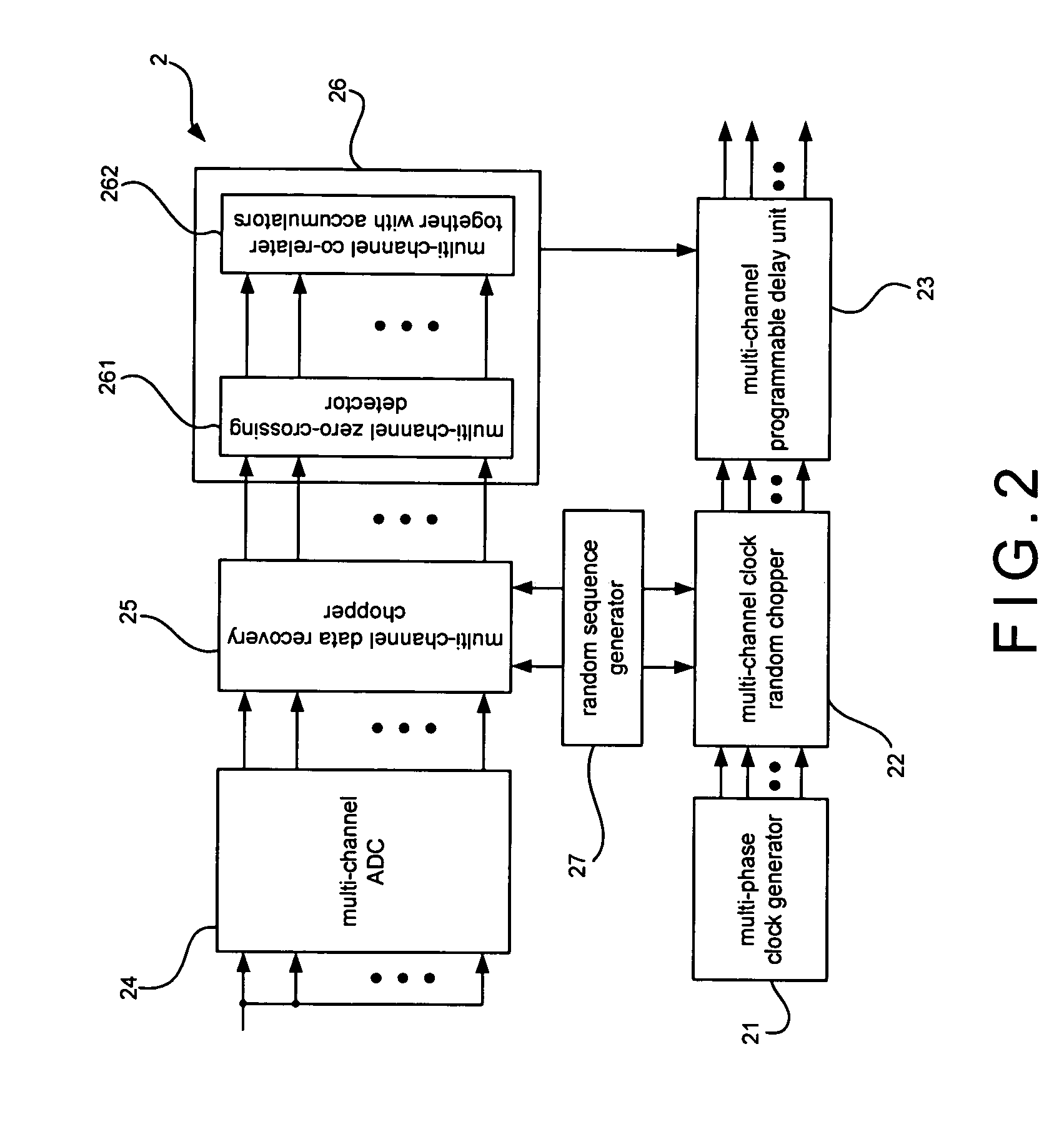
[0021] Please refer to FIG. 2, which is a structural view showing a second preferred embodiment. As shown in the figure, the second embodiment is a multi-channel time-interleaved ADC 2, comprising a multi-phase clock generator 21, a multi-channel clock random chopper 22, a multi-channel programmable delay unit 23, a multi-channel ADC 24, a multi-channel data recovery chopper 25, a multi-channel CP 26 and a random sequence generator 27. Therein, the multi-channel CP 26 comprises a multi-channel zero-crossing detector 261 and a multi-channel co-relater together with accumulators 262; the multi-channel co-relater together with accumulators 262 comprises a co-relater and a plurality of accumulators; and, the accumulator is a flexible-symbol accumulator or a general accumulator. The multi-phase clock generator 21 generates a plurality of phases; and, the number of the phases, which has to be an even number, is obtained by dividing a sampling period of each ADC by a timing difference of e...


PUM


Abstract

An analog-to-digital converter (ADC) having a two-channel or multi-channel structure processes background timing calibration. Signals from the ADC are directly compared for the calibration. Additional signal or interruption of circuit is not required. A dynamic calibration is processed. A timing-skew error is kept in a low level and a process mismatch is not a concern. Moreover, sampling frequency and input signal frequency are improved. A high sampling frequency and a high speed of signal inputting are achieved; and chip area can be greatly shrunk because the extra calibration circuits are simple digital circuits.

Description

FIELD OF THE INVENTION [0001] The present invention relates to an analog-to-digital converter; more particularly, relates to dynamically calibrating timing of narrow-band signals and wide-band signals in a successive circulation by using a two-channel or multi-channel time-interleaved analog-to-digital converter having background timing calibration without interruption of circuit. DESCRIPTION OF THE RELATED ARTS [0002] General timing-skew calibrations for a time-interleaved analog-to-digital converter includes the following method [0003] a. Foreground calibration method: Before running the circuit , a standard input signal is generated as a calibration authority for a calibration of timing-skew error of each various phase. But, because timing skew will slightly changes with the temperature and the outside environment on running the circuit, a main disadvantage of this method is that a dynamic calibration of timing-skew error is not available and the converter becomes inferior after ...

Claims


Application Information

Patent Timeline
IPC IPC(8): H03M1/10
CPCH03M1/1215H03M1/1004
Inventor WANG, CHUNG-YIWU, JIEH-TSORNG
Owner NATIONAL CHIAO TUNG UNIVERSITY
Learn More