
Soft magnetic material and powder magnetic core

Active Publication Date: 2007-08-23
SUMITOMO ELECTRIC IND LTD
View PDF12 Cites 2 Cited by
  • Summary
  • Abstract
  • Description
  • Claims
  • Application Information

AI Technical Summary

Benefits of technology

[0015] In this soft magnetic material, the proportion of the lubricant formed as fine particles is at least 0.001 percent by mass, making it possible to obtain adequate lubrication between composite magnetic particles during compacting when making a powder magnetic core. Also, by having the proportion of the lubricant formed as fine particles be no more than 0.1 percent by mass, the distance between the metal magnetic particles does not become too big. This makes it possible to prevent the creation of demagnetizing fields between the metal magnetic particles (created because the formation of magnetic poles in the metal magnetic particles leads to energy loss), and increased hysteresis loss resulting from demagnetizing fields can be limited. Also, by limiting the volume proportion of the non-magnetic layer in the powder magnetic core, it is possible to prevent saturation magnetic flux density from decreasing.
[0046] With the present invention as described above, it is possible to provide a soft magnetic material that can provide desired magnetic characteristics after compacting and a powder magnetic core made from this soft magnetic material. Also, with the present invention, it is possible to provide a powder magnetic core, a soft magnetic material, and method for making a powder magnetic core having desired magnetic characteristics.

Problems solved by technology

This makes it possible to prevent the creation of demagnetizing fields between the metal magnetic particles (created because the formation of magnetic poles in the metal magnetic particles leads to energy loss), and increased hysteresis loss resulting from demagnetizing fields can be limited.
As a result, even if insulating coating rubs against each other during compacting, significant friction is not generated.

Method used


Image

  • Soft magnetic material and powder magnetic core
  • Soft magnetic material and powder magnetic core
  • Soft magnetic material and powder magnetic core

Examples


first embodiment

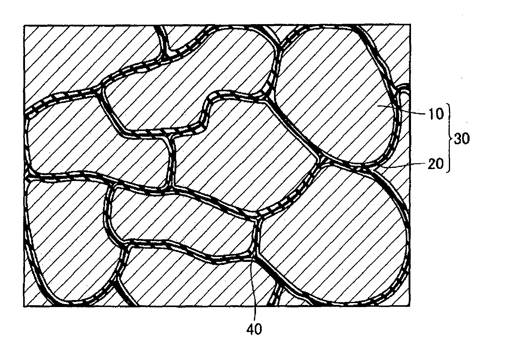
[0065] As shown in FIG. 1, a powder magnetic core includes a plurality of composite magnetic particles 30 formed from a metal magnetic particle 10 and an insulative coating 20 surrounding the surface of the metal magnetic particle 10. An organic matter 40 is present between the plurality of the composite magnetic particles 30. The composite magnetic particles 30 are bonded to each other by the organic matter 40 or by the engagement of the projections and indentations of the composite magnetic particles 30.

[0066] A soft magnetic material according to this embodiment used to make the powder magnetic core shown in FIG. 1 includes: the plurality of composite magnetic particles 30 formed from the metal magnetic particle 10 and the insulative coating 20; and a lubricating powder (a lubricant in the form of fine particles) added at a predetermined proportion to the composite magnetic particles 30 and serving as the organic matter 40 in the powder magnetic core of FIG. 1 when compacted.

[0...

first example

[0080] The examples described below were used to evaluate the soft magnetic material according to the first embodiment and the powder magnetic core made from this soft magnetic material.

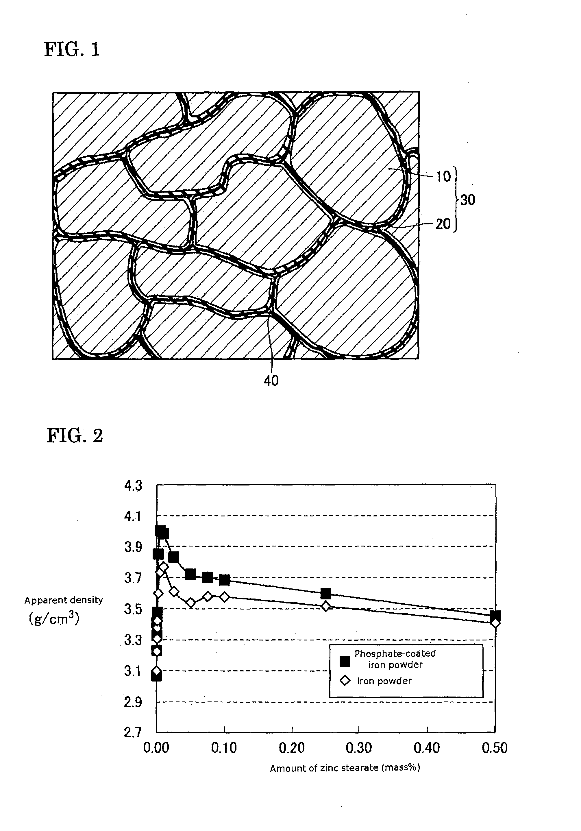
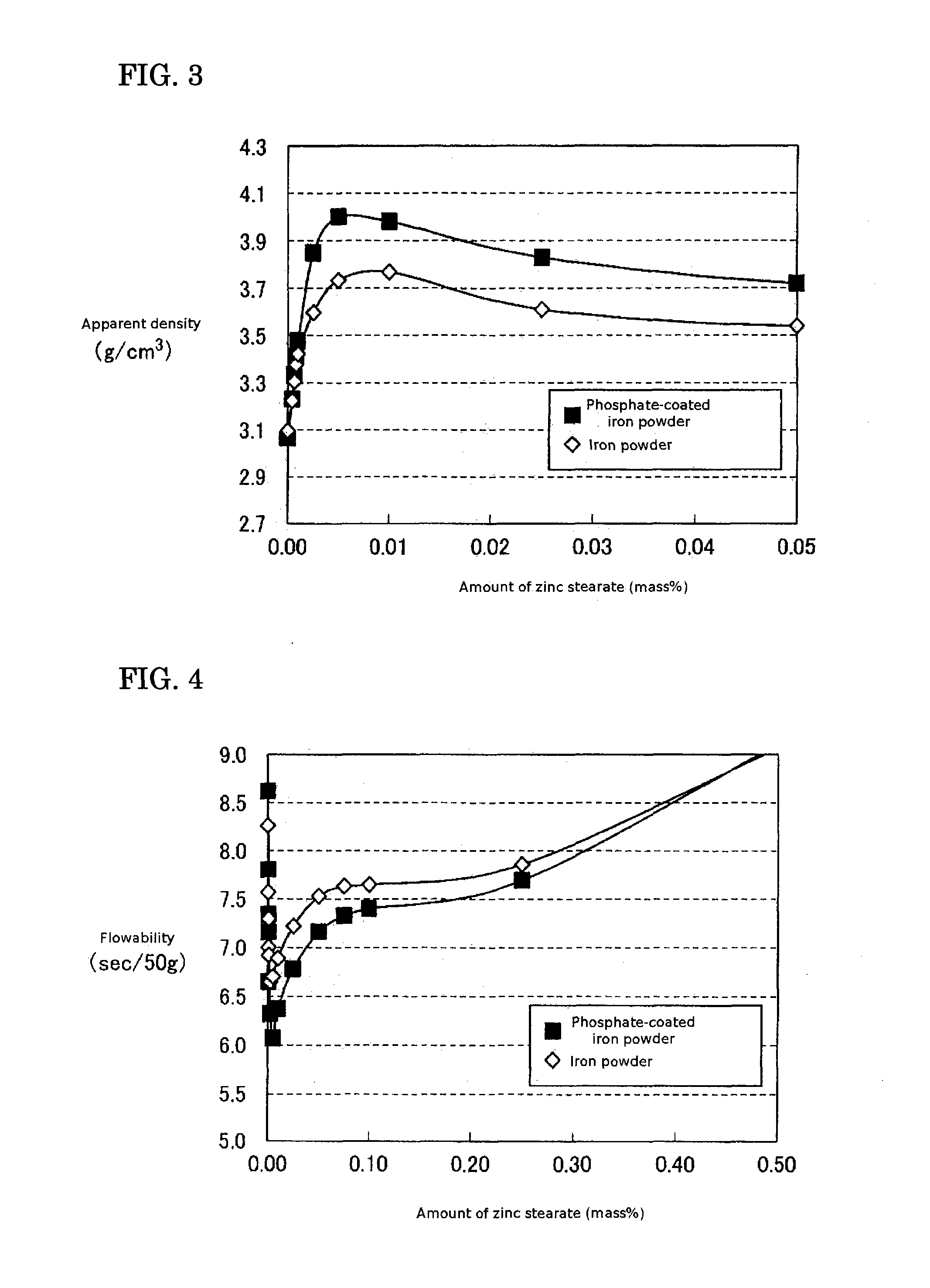
[0081] First, for the composite magnetic particles 30, a predetermined amount of zinc stearate (product name “MZ-2” from NOF Corp. Ltd., 0.8 microns mean particle diameter) is added as a lubricating powder to phosphate-coated iron powder (product name “Somaloy500” from Hoganas Corp.). Next, a V-mixer is used to mix for 1 hour. Multiple types of soft magnetic materials containing different amounts of zinc stearate relative to the phosphate-coated iron powder were prepared. For comparison, multiple types of soft magnetic materials containing different amounts of zinc stearate added to iron powder with no phosphate coating (product name “ABC100.30” from Hoganas Corp.) were prepared.

[0082] In order to evaluate lubrication of the soft magnetic material, apparent density according to “JIS Z 2504” and flo...

second example

[0085] Next, zinc stearate from NOF Corp. Ltd. was prepared as the lubricating powder. Dry sieving was performed to sort the powder into four type of zinc stearate with mean particle diameters of 0.8 microns, 1.6 microns, 2.3 microns, and 7.5 microns. Next, predetermined amounts were added to phosphate-coated iron powder (product name “Somaloy500” from Hoganas Corp.) serving as the composite magnetic particles 30, and mixing was performed as in the first example. This resulted in multiple types of soft magnetic materials with different zinc stearate mean particle diameters and different amounts of zinc stearate added to the phosphate-coated iron powder.

[0086] The soft magnetic materials prepared in this manner were measured for apparent density and flowability, as in the first example. FIG. 7 and FIG. 9 are the measurement results from FIG. 6 and FIG. 8 respectively. The measurement results for zinc stearate amounts of 0 to 0.05 percent by mass are shown in detail.

[0087] As FIG. 6...


PUM

PropertyMeasurementUnit
Fractionaaaaaaaaaa
Percent by massaaaaaaaaaa

Abstract

A soft magnetic material includes: a plurality of composite magnetic particles formed from a metal magnetic particle and an insulative coating surrounding a surface of the metal magnetic particle and containing metallic salt phosphate and / or oxide; and a lubricant formed as fine particles added at a proportion of at least 0.001 percent by mass and no more than 0.1 percent by mass relative to the plurality of composite magnetic particles. With this structure, superior lubrication is provided during compacting and desired magnetic characteristics can be obtained after compacting.

Description

CROSS-REFERENCE TO PRIOR APPLICATIONS [0001] This application is a U.S. national phase application under 35 U.S.C. §371 of International Patent Application No. PCT / JP2005 / 005887, filed Mar. 29, 2005, and claims the benefit of Japanese Application No.2004-103686, filed Mar. 31, 2004, and Japanese Application No. 2004-103687, filed Mar. 31, 2004, all of which are incorporated by reference herein. The International Application was published in Japanese on Oct. 13, 2005 as International Publication No. WO 2005 / 096324 A1 under PCT Article 21(2).TECHNICAL FIELD [0002] The present invention relates generally to a soft magnetic material and powder magnetic core. More specifically, the present invention relates to a soft magnetic material and powder magnetic core equipped with a plurality of metal magnetic particles covered with insulative coating. BACKGROUND ART [0003] A first background technology will be described. In products such as electromagnetic valves and motors, there has been a tr...

Claims


Application Information

Patent Timeline
IPC IPC(8): H01F1/14B22F1/16B22F3/00H01F1/24H01F1/33H01F27/255H01F41/02
CPCB22F1/02B22F2998/10H01F1/24H01F1/33H01F41/0246B22F3/02B22F3/24B22F1/16
Inventor HIROSE, KAZUHIROTOYODA, HARUHISANISHIOKA, TAKAOIGARASHI, NAOTOMAEDA, TORUSHIMADA, YOSHIYUKI
Owner SUMITOMO ELECTRIC IND LTD
Learn More