
Large area deposition in high vacuum with high thickness uniformity

a technology of high vacuum and uniform thickness, applied in vacuum evaporation coating, crystal growth process, coating, etc., can solve the problems of poor utilization efficiency of expensive and toxic reactants, inability to scale up vacuum deposition to industrial applications, and inability to achieve high-efficiency vacuum deposition. achieve the effect of precise control of flow throughpu

Inactive Publication Date: 2007-08-23
ECOLE POLYTECHNIQUE FEDERALE DE LAUSANNE (EPFL)
View PDF8 Cites 4 Cited by
  • Summary
  • Abstract
  • Description
  • Claims
  • Application Information

AI Technical Summary

Benefits of technology

The invention is a new small gas source for vacuum deposition that can create highly uniform thickness on large areas with small reactor size and high precursor efficiency use. The source design is also compatible with light-assisted deposition. The reactor design allows for the distribution of molecules on the substrate to be calculated mathematically. The sources are chosen for their low temperatures, multiple sources, small size, stability, reproducibility, high throughput, and ideal conditions for modeling. The small aspect ratio between the hole thickness and hole diameter ensures effusion without opaque regimes. The non-focused sources minimize misalignments effects on thickness uniformity and the reduced precursor flow outside the deposition area reduces complications. The reactor design with a single pre-chamber connected to all the effusing sources is simple and reproducible, and cost-effective. The patent also describes the possibility of graded composition and co-deposition of different materials with controlled composition and thickness uniformity.

Problems solved by technology

It is commonly believed that the alternative approach of vacuum deposition is difficult to scale up to industrial applications.
Furthermore, vacuum deposition is also known to be inherently more expensive and difficult with these two drawbacks increasing as lower pressures are aimed at.
As a summary, we can report the following points: CVD processes have a much higher production capacity, but suffer from poor utilization efficiency of the expensive and toxic reactants gases (L. M. Fraas, in U.S. Pat. No. 4,828,021).
In opposition, MBE devices are not easily scalable to meet the needs of the growing market.
Concentric annular arrays of sources have been proposed to provide different gases (Frijlink U.S. Pat. No. 4,961,399), but several problems are still open.
Rotation, or planetary motion, was also introduced to provide uniform thickness (Frijlink U.S. Pat. No. 4,961,399), but light processes are incompatible with such a motion.
This is the closest result found for patent to our proposed invention, but uniformity is only about 5-10% and is hence not suitable to many applications.
What can be said is that no global solution has been found up to now and the above cited patent document have only solved some of the specific mentioned problems.
In particular, viscous and transition regimes are poorly, if not at all, compatible with light (electron ion)-assisted processes.
Furthermore, flexibility is poor to achieve good thickness uniformity (inter-correlation of deposition parameters), while up-scaling to larger substrates or upgrading to new materials is not straightforward and can be very difficult.
These effects are however very limited to the working temperatures below 100-200° C. required avoiding chemical precursor adsorption and sufficient vapour pressure.
Another effect that can make fail attempts to produce uniform impinging rate on the deposition area is that molecules can bounce on walls inside the deposition chamber.
These scattered molecules would hence lead to uncontrolled deposition.
The difficulty in the molecular flow regime is to achieve simultaneously both high thickness uniformity and high growth rates [4], which are usually related to high efficiency use of precursor [4, 5], and high initial investment costs [1] as reducing the size of the reactor usually allows reduced equipment costs, but also leads to poor thickness uniformity.
Small apertures have not been used very often in physical vapour deposition sources because difficulties appear due to regulation of each source.
These sources are furthermore expensive and unstable as the vapour condensation and evaporation can modify the effusion.
Physical reasons may limit this tilting angle that is not always optimal for evaporation sources due to liquid geometry level considerations [5].
Finally, smaller sources compared to a single large source are interesting as light induced or light enhanced deposition is incompatible with substrate motion.
One of the problems in MBE sources is that the source angular distribution may vary to a large extent as a function of the filling level.
This leads to poorly controllable angular distributions of effusing molecules with time [23].
Another error that can account for different angular distributions is that the source dimension aperture can have a deep impact on the molecular distribution.
However, such collimated sources lead to several problems.
The obtained results reported by the scientific community with regard to thickness uniformity deposition are in general difficult to evaluate if the parameters of reactor size versus substrate size are introduced.
A systematic approach and a good understanding of these parameters are still lacking.

Method used


Image

  • Large area deposition in high vacuum with high thickness uniformity
  • Large area deposition in high vacuum with high thickness uniformity
  • Large area deposition in high vacuum with high thickness uniformity

Examples


Embodiment Construction

[0060] A. The Effusion Source

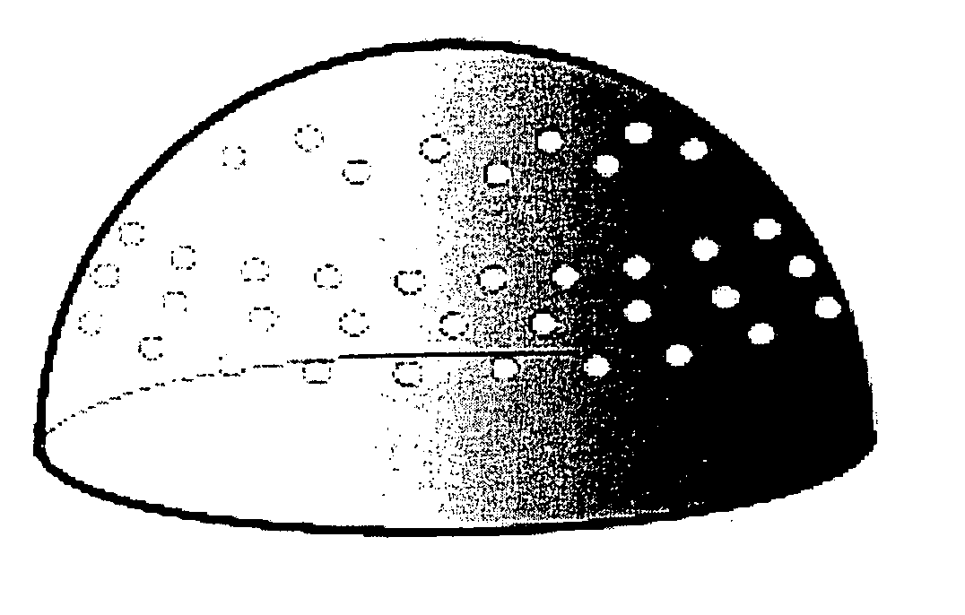
[0061] A typical effusion source is a hole of 0.5 mm drilled in a foil of 0.05 mm of thickness between a reservoir (pre-chamber) with a pressure of 10−3-10−2 mbar and the deposition chamber with a pressure below 10−3mbar. The hole dimensions however, depend on the pressure in the pre-chamber and on the substrate size, and could vary from 0.001 and 50 mm. Furthermore, the thickness of the hole is about one order of magnitude (or more) smaller than the diameter, while the distance of the source to the deposition area is one order of magnitude (or more) larger than the diameter of the hole.

[0062] B. Disposition and General Description of the Sources

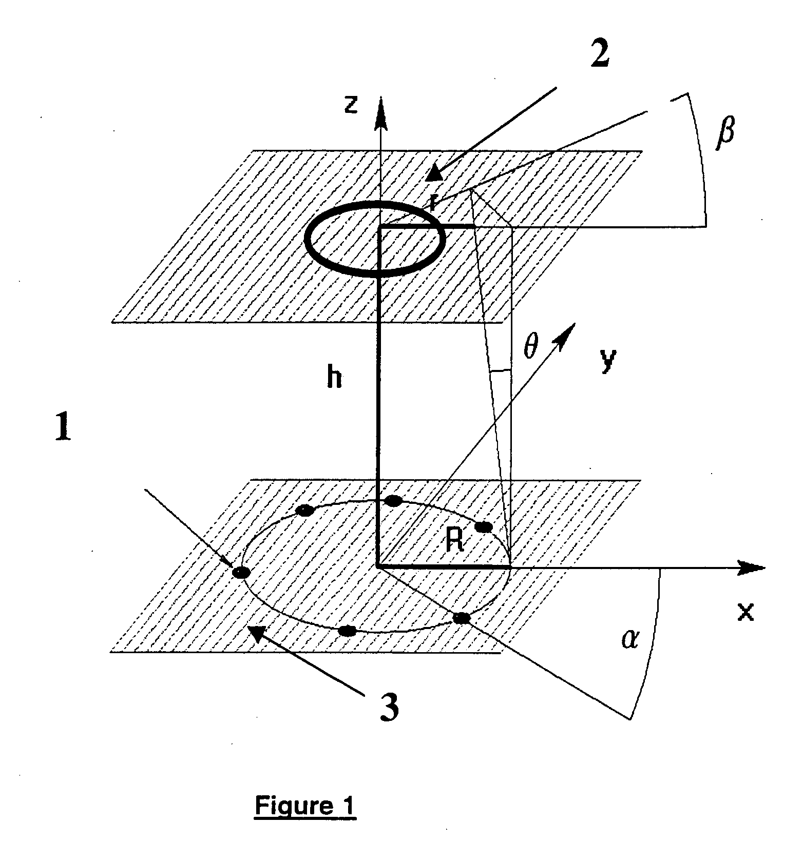
[0063] The combination of several sources may allow substrate rotation avoidance. Several holes are uniformly distributed on an annular geometry (see FIG. 1). The formula that describes the distribution of impinging molecules on a planar surface for several cosn distributions of the effusion sources distribute...


PUM

PropertyMeasurementUnit
temperaturesaaaaaaaaaa
thicknessaaaaaaaaaa

Abstract

The invention relates to an effusing source for film deposition made of a reservoir comprising one hole characterized by the fact that the hole diameter is less than one order of magnitude than the mean free path of the molecules determined by the pressure and its thickness is at least one order of magnitude smaller than the diameter. Preferably the source has several holes.

Description

FIELD OF THE INVENTION [0001] The present invention relates to thermal or laser-assisted (electron or ion beam-assisted) film deposition with chemical precursors in the molecular regime. STATE OF THE ART [0002] The business and technology of large area vacuum coatings have made significant progresses in the last two decades and are still proceeding with great expectation for the future [1, 2]. In particular, we can mention typical applications as architectural and automotive glasses, solar cells, and micro-optoelectronics applications that require larger and larger substrates to reduce costs. [0003] It is commonly believed that the alternative approach of vacuum deposition is difficult to scale up to industrial applications. Furthermore, vacuum deposition is also known to be inherently more expensive and difficult with these two drawbacks increasing as lower pressures are aimed at. However the use of vacuum deposition has some advantages for industrial applications. Indeed, high-thr...

Claims


Application Information

Patent Timeline
Patent Type & Authority Applications(United States)
IPC IPC(8): C23C16/00C23C14/24C30B23/06
CPCC30B23/066C23C14/243C23C14/24C23F4/02
Inventor BENVENUTI, GIACOMOHALARY-WAGNER, ESTELLEAMOROSI, SIMONEHOFFMANN, PATRIK
Owner ECOLE POLYTECHNIQUE FEDERALE DE LAUSANNE (EPFL)
Learn More