
Balloon control apparatus

a control apparatus and balloon technology, applied in the field of balloon control apparatus, can solve the problems of poor operation ease, achieve the effects of reducing the difference in time, reducing the difficulty of operation, and improving the ease of operation

Inactive Publication Date: 2007-08-16
FUJI PHOTO OPTICAL CO LTD
View PDF6 Cites 15 Cited by
  • Summary
  • Abstract
  • Description
  • Claims
  • Application Information

AI Technical Summary

Benefits of technology

[0012]The invention provides a balloon control apparatus that can eliminate (or lessen) the difference in time until the balloon internal pressure reaches a predetermined pressure (namely, the time until the balloon is fixed) regardless of the type of digestive tract.
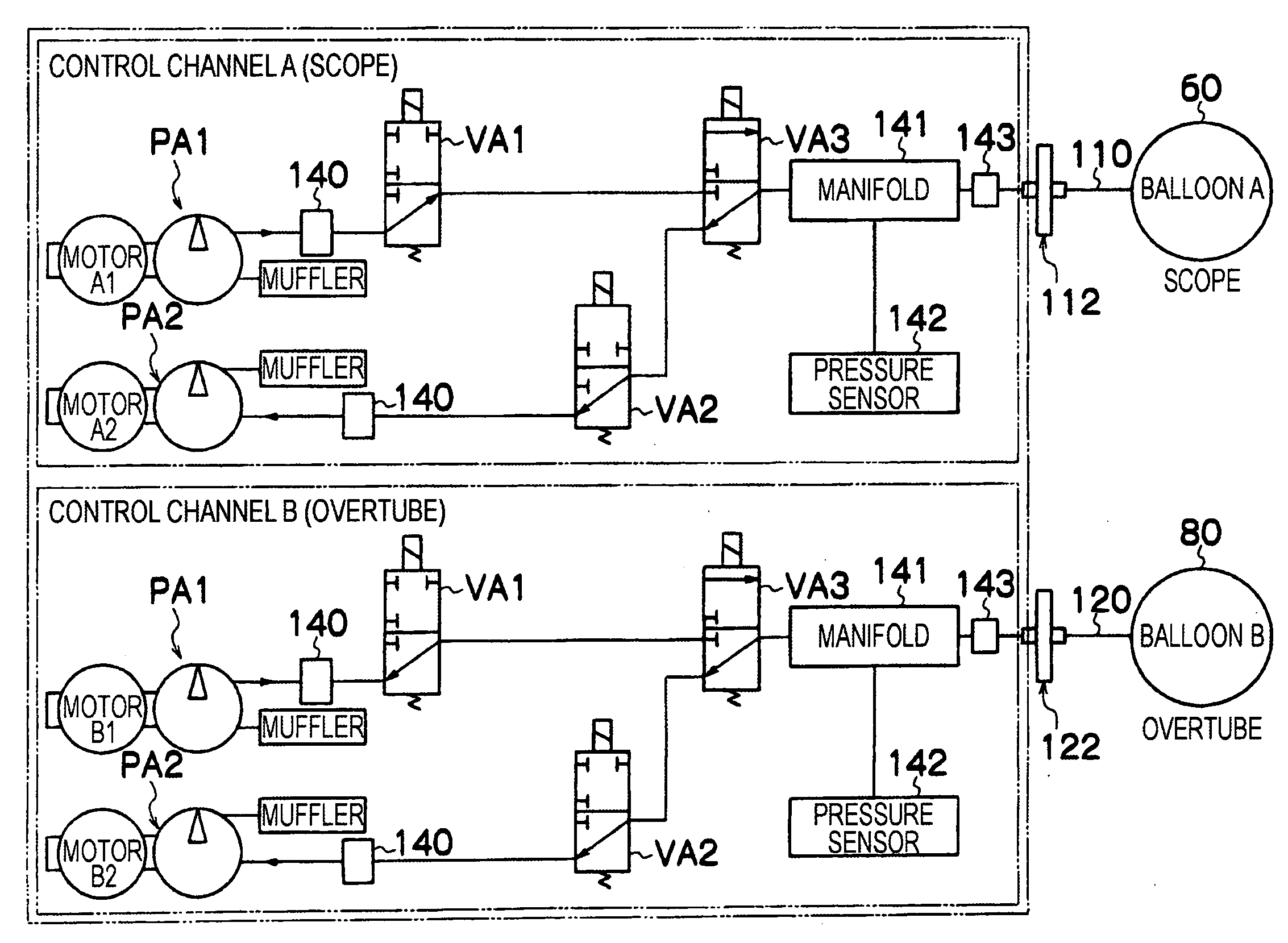
[0016]According to this configuration, it is made possible to set the air supply flow rate (or exhaust flow rate) in accordance with the intracoelomic part into which the endoscope insertion section, etc., is to be inserted (for example, digestive tract of small intestine, large intestine, etc.,) through the setting section. That is, it is made possible to set the flow rate in response to the intracoelomic part (for example, the type of digestive tract) in such a manner that if a small intestine is selected, flow rate R is set or if a large intestine is selected, flow rate R1×3 is set. Formerly, the time required until the balloon expands and contacts the intestinal wall and predetermined pressure P is reached was about 10 seconds for the small intestine and about 30 seconds for the large intestine. To the contrary, according to this above configuration, the flow rates are set as described above. Thereby, the time until the internal pressure of the balloon reaches the setup pressure P (namely, the time until the balloon is fixed) in the large intestine becomes about one third and becomes roughly equal to the required time in the small intestine. That is, it is made possible to eliminate (or lessen) the difference in time until the internal pressure of the balloon reaches the setup pressure P (namely, the time until the balloon is fixed) regardless of the type of digestive tract. The ease of operation is improved and efficient inspection and medical treatment are made possible.
[0018]According to this configuration, it is made possible to set the air supply flow rate (or exhaust flow rate) in accordance with the procedure of the endoscope, such as a single balloon method or a double balloon method, through the setting section. That is, it is made possible to set the flow rate in accordance with the procedure in such a manner that if the operator selects the single balloon method, flow rate R1 is set and that if the operator selects the double balloon method, flow rate R2 (R1>R2) is set. Formerly, the single balloon method and the double balloon method were roughly the same in the time required until the balloon expands and contacts the intestinal wall and the predetermined pressure P is reached. To the contrary, according to the above configuration, the flow rates are set as described above. Thereby, the expansion and contraction time of the single balloon is shortened and return of the pulled-in intestinal tract can be lessened. As a result, the single balloon method would also make it possible to improve the ease of operation and conduct efficient inspection and medical treatment.
[0027]According to the invention, it is made possible to provide the balloon control apparatus that can eliminate (or lessen) the difference in time until a balloon is fixed (namely, the time until the balloon internal pressure reaches the setup pressure P) regardless of the type of digestive tract; the ease of operation improves and efficient inspection and medical treatment are made possible.

Problems solved by technology

Thus, in the endoscope with the balloon according to the related art, since air supply to the balloon (or exhaust from the balloon) is executed at a predetermined flow rate, the time until the balloon internal pressure reaches a predetermined pressure (namely, the time until the balloon is fixed) varies depending on the type of digestive tract, and the ease of operation is poor.

Method used


Image

  • Balloon control apparatus
  • Balloon control apparatus
  • Balloon control apparatus

Examples


Embodiment Construction

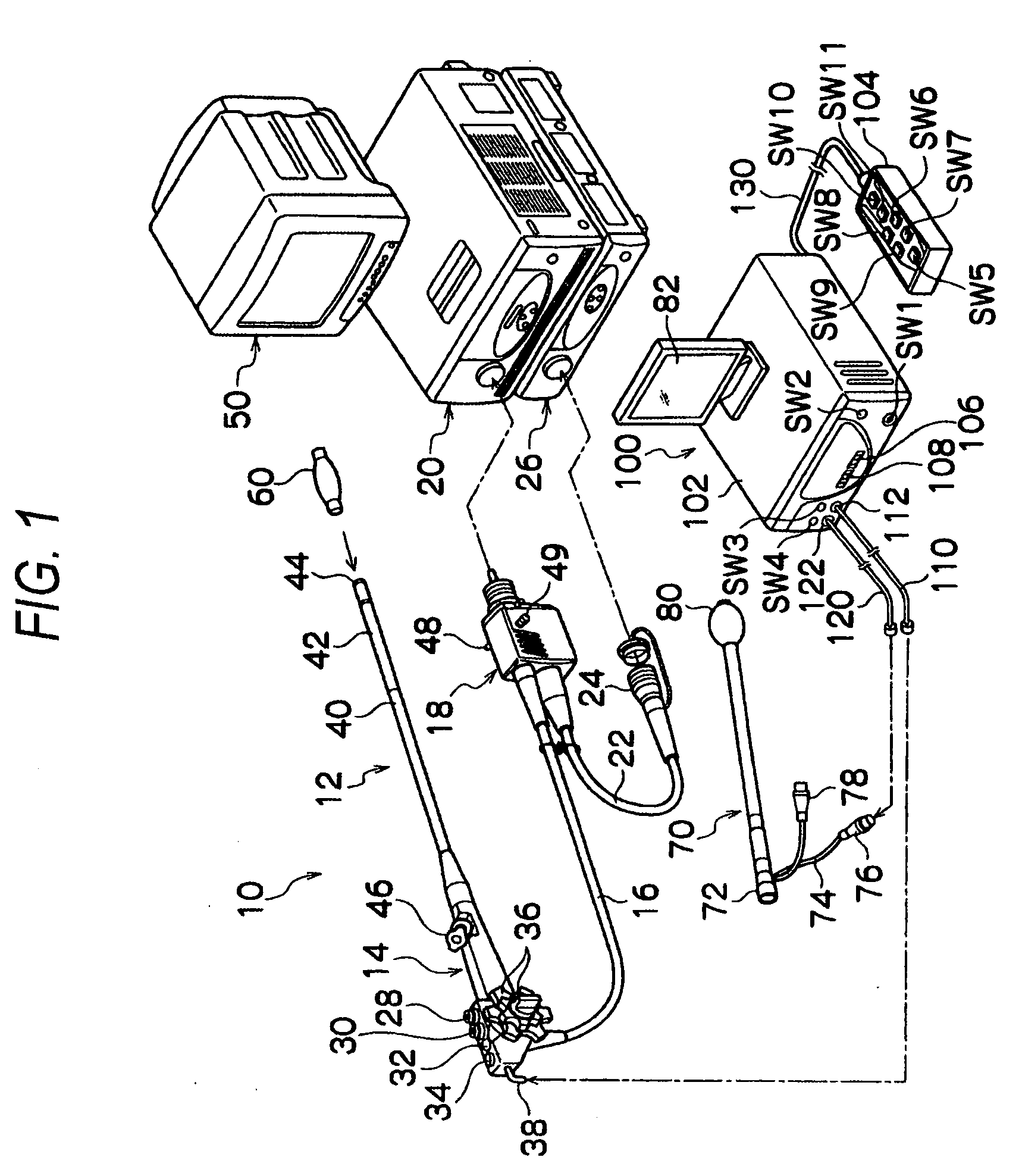
[0038]A balloon control apparatus for an endoscope according to exemplary embodiments of the invention will be described in detail with reference to the accompanying drawings. FIG. 1 is a system configuration drawing to show an endoscope system incorporating a balloon control apparatus according to one embodiment of the invention. As shown in FIG. 1, the endoscope system mainly includes an endoscope 10, an insertion aid instrument 70, and a balloon control apparatus 100.

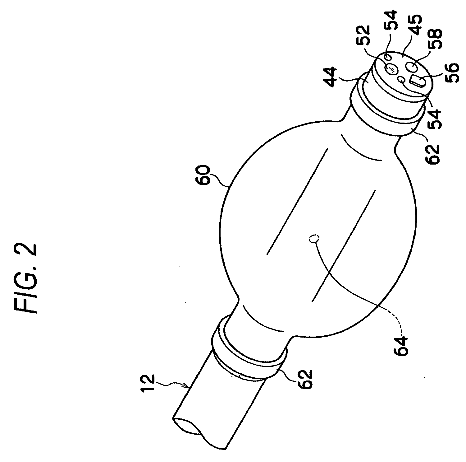
[0039]As shown in FIG. 1, the endoscope 10 includes a handheld operation section 14 and an insertion section 12 which is jointed to the handheld operation section 14 and which is inserted into a body cavity. A universal cable 16 is connected to the handheld operation section 14. An LG connector 18 is provided at the tip of the universal cable 16. The LG connector 18 is detachably joined to a light source unit 20, to thereby send illumination to an illumination optical system 54 (described later with reference to FIG....


PUM


Abstract

A balloon control apparatus includes a balloon, a flow rate adjustment section, a setting section and a control section. The balloon is attached to an insertion section of an endoscope and / or an insertion aid instrument for guiding insertion of the insertion section of the endoscope. The flow rate adjustment section adjusts an air supply flow rate to the balloon and / or an exhaust flow rate from the balloon. The setting section sets the air supply flow rate and / or the exhaust flow rate. The control section controls the flow rate adjustment section so that the air supply flow rate to the balloon and / or the exhaust flow rate from the balloon become the air supply flow rate and / or the exhaust flow rate set by the setting section.

Description

BACKGROUND OF THE INVENTION[0001]1. Technical Field[0002]This invention relates to a balloon control apparatus and in particular to a balloon control apparatus that can eliminate (or lessen) difference in time until the balloon internal pressure reaches a predetermined pressure (namely, the time until the balloon is fixed) regardless of the type of digestive tract.[0003]2. Description of the Related Art[0004]Hitherto, in the field of an endoscope, the following endoscope with a balloon has been known. That is, from the viewpoint of fixing to a body cavity an endoscope insertion section (or an insertion aid instrument for guiding insertion of the endoscope insertion section) inserted into the body cavity, the endoscope has the balloon, which is expanded by air supply and contracted by exhaust, in the endoscope insertion section (or the insertion aid instrument; see JP 2002-301019 A and JP 2004-337288 A).[0005]In the endoscope with the balloon, an air pump is connected to the balloon ...

Claims


Application Information

Patent Timeline
Patent Type & Authority Applications(United States)
IPC IPC(8): A61B1/00A61B1/12A61F2/958
CPCA61B1/00082A61M2205/3337A61M25/1018A61B1/015A61M25/10188A61M2039/0279A61M25/10184
Inventor SEKIGUCHI, TADASHI
Owner FUJI PHOTO OPTICAL CO LTD
Learn More