
Three-dimensional imaging system for robot vision

a three-dimensional imaging and robot vision technology, applied in the field of three-dimensional imaging systems for robot vision, can solve the problems of difficult to achieve the efficiency and effectiveness of difficult to create corresponding artificial sensory systems, and difficult to achieve the effect of efficiency and effectiveness in a conventional robot vision system. , to achieve the effect of compact imaging device, simple camera calibration, and substantial sharp imag

Active Publication Date: 2007-08-16
STEREO DISPLAY
View PDF87 Cites 11 Cited by
  • Summary
  • Abstract
  • Description
  • Claims
  • Application Information

AI Technical Summary

Benefits of technology

The present invention provides a three-dimensional imaging system for robot vision that can generate an all-in-focus image and three-dimensional position information of an object. The system uses a variable focal length micromirror array lens (MMAL) and a camera system with one or more two-dimensional image sensors taking images at different focal planes. The image processing unit extracts in-focus pixels or areas from each image to generate a corresponding in-focus depthwise image, which represents a portion of the object or scene having the same image depth. The system can search and track an object of interest in a wide field of view with low resolution. The three-dimensional position information of the object is necessary for robot's object manipulation and navigation, and it also enables accurate and robust object identification.

Problems solved by technology

In the early stages of adopting these human sensing procedures, it was very difficult to create corresponding artificial sensory systems because of complexity, limited resources, and a lack of knowledge.
However, these processes can be very erroneous and time-consuming.
However, it is difficult to accomplish such efficiency and effectiveness in a conventional robot vision system since those changes are usually performed by a complicated macroscopic servo mechanism.

Method used


Image

  • Three-dimensional imaging system for robot vision
  • Three-dimensional imaging system for robot vision
  • Three-dimensional imaging system for robot vision

Examples


Embodiment Construction

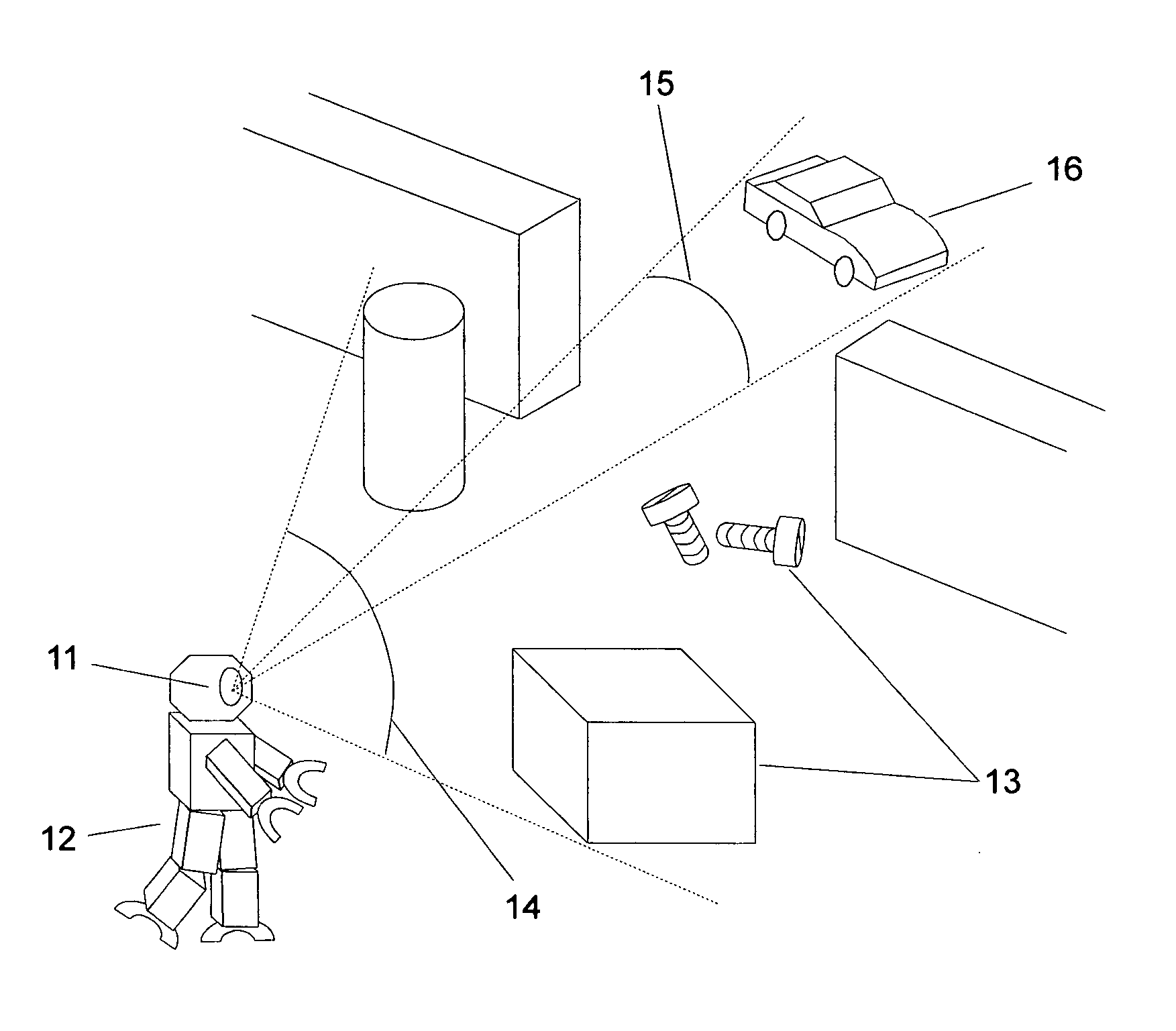
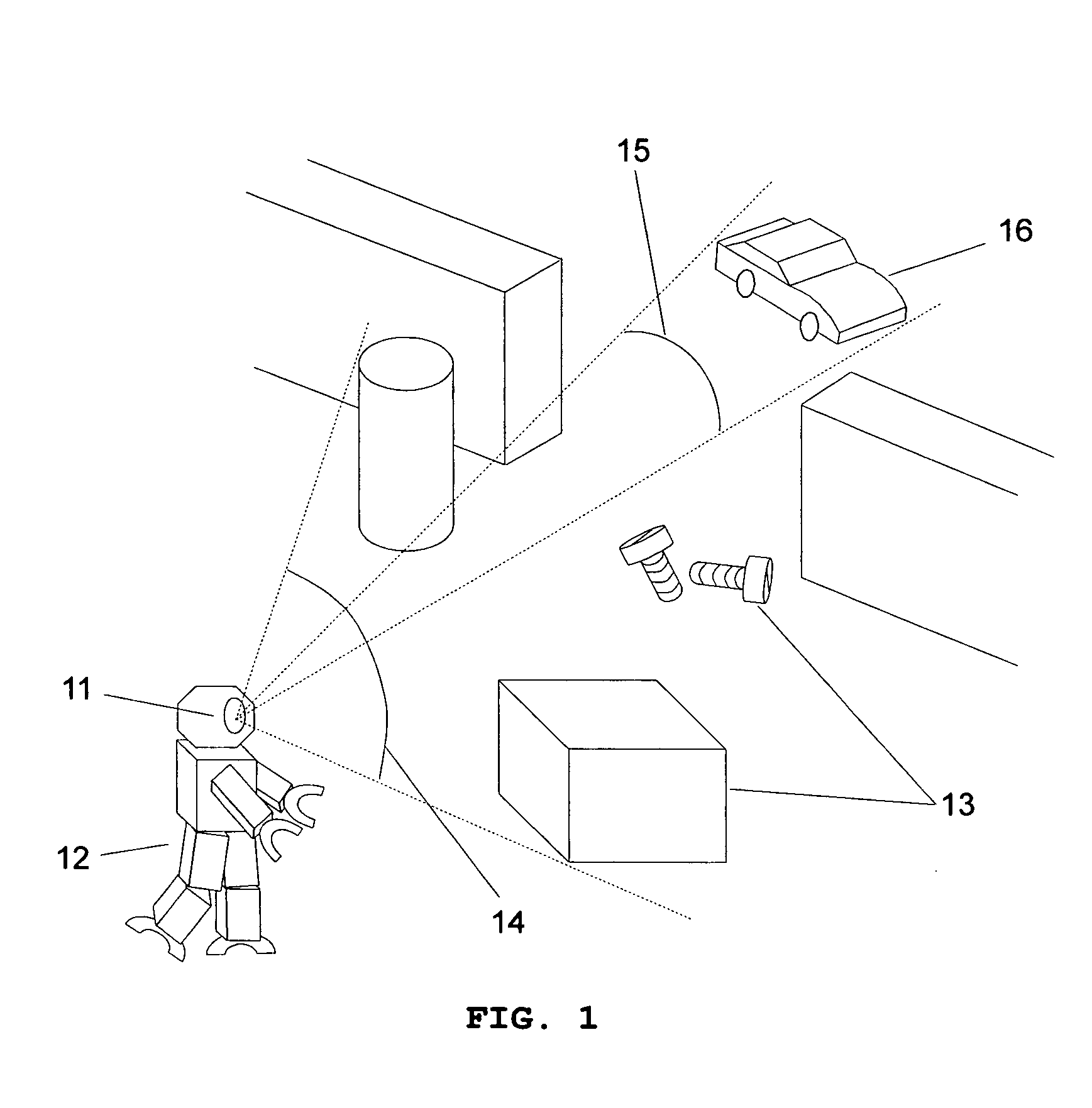
[0032]FIG. 1 illustrates a robot vision system 11 of a robot 12 working in various environments with different tasks including manipulation, object identification, searching and tracking an object of interest, and navigation in known and unknown territories. The image sensor (not shown) receives two-dimensional images with different focal planes that are shifted by changing the focal length of the variable focal length MMAL. The image processing unit (not shown) generates all-in-focus images and calculates three-dimensional position data of objects 13. Using all-in-focus images and three-dimensional position information of the object, the robot vision system can perform manipulation, object identification, searching and tracking a still or a moving object, navigation, and the like. It is efficient that the imaging system uses a wide field of view 14 to search an object of interest from the scene and then use a narrow field of view 15 to identify and track the object precisely. When ...


PUM


Abstract

The present invention provides a three-dimensional imaging system for robot vision, which is capable of three-dimensional positioning of objects, object identification, searching and tracking of an object of interest, and compensating the aberration of the system. The three-dimensional imaging system for robot vision comprises one or more camera systems, each of which has at least one variable focal length micromirror array lens, an imaging unit, and an image processing unit. The variable focal length micromirror array lens used in the three-dimensional imaging system for robot vision has unique features including a variable focal length, a variable focal axis, and a variable field of view with a fast response time.

Description

REFERENCES TO RELATED APPLICATIONS [0001] This application is a continuation-in-part of, and claims priority to U.S. patent application Ser. No. 10 / 806,299 filed Mar. 22, 2004 (Docket No. 1802.03), U.S. patent application Ser. No. 10 / 822,414 filed Apr. 12, 2004 (Docket No. 1802.04), U.S. patent application Ser. No. 10 / 983,353 filed Nov. 8, 2004 (Docket No. 1802.013Con), U.S. patent application Ser. No. 10 / 872,241 filed Jun. 18, 2004 (Docket No. 1802.011), U.S. patent application Ser. No. 10 / 893,039 filed Jul. 16, 2004 (Docket No. 1802.012), U.S. patent application Ser. No. 10 / 979,619 filed Nov. 2, 2004 (Docket No. 1802.18), and U.S. patent application Ser. No. 10 / 979,624 filed Nov. 2, 2004 (Docket No. 1802.19), all of which are hereby incorporated by reference.FIELD OF INVENTION [0002] The present invention relates to a three-dimensional imaging system for robot vision comprising at least one micromirror array lens. BACKGROUND OF INVENTION [0003] Robots have been widely used in the ...

Claims


Application Information

Patent Timeline
Patent Type & Authority Applications(United States)
IPC IPC(8): G02B15/14
CPCG02B26/0833
Inventor SEO, CHEONG SOOBAEK, SANG HYUNECHO, GYOUNG IL
Owner STEREO DISPLAY
Learn More