Hydraulic control apparatus for vehicular fluid- actuated power transmitting device provided with lock-up clutch
a technology of hydraulic control apparatus and transmission device, which is applied in the direction of heat measurement, instruments, gearing, etc., can solve the problems of failure to improve the fuel economy of the vehicle, delay in the temperature of the working fluid, etc., and achieve the effect of preventing an excessive rise of the pressure of the working fluid
- Summary
- Abstract
- Description
- Claims
- Application Information
AI Technical Summary
Benefits of technology
Problems solved by technology
Method used
Image
Examples
first embodiment
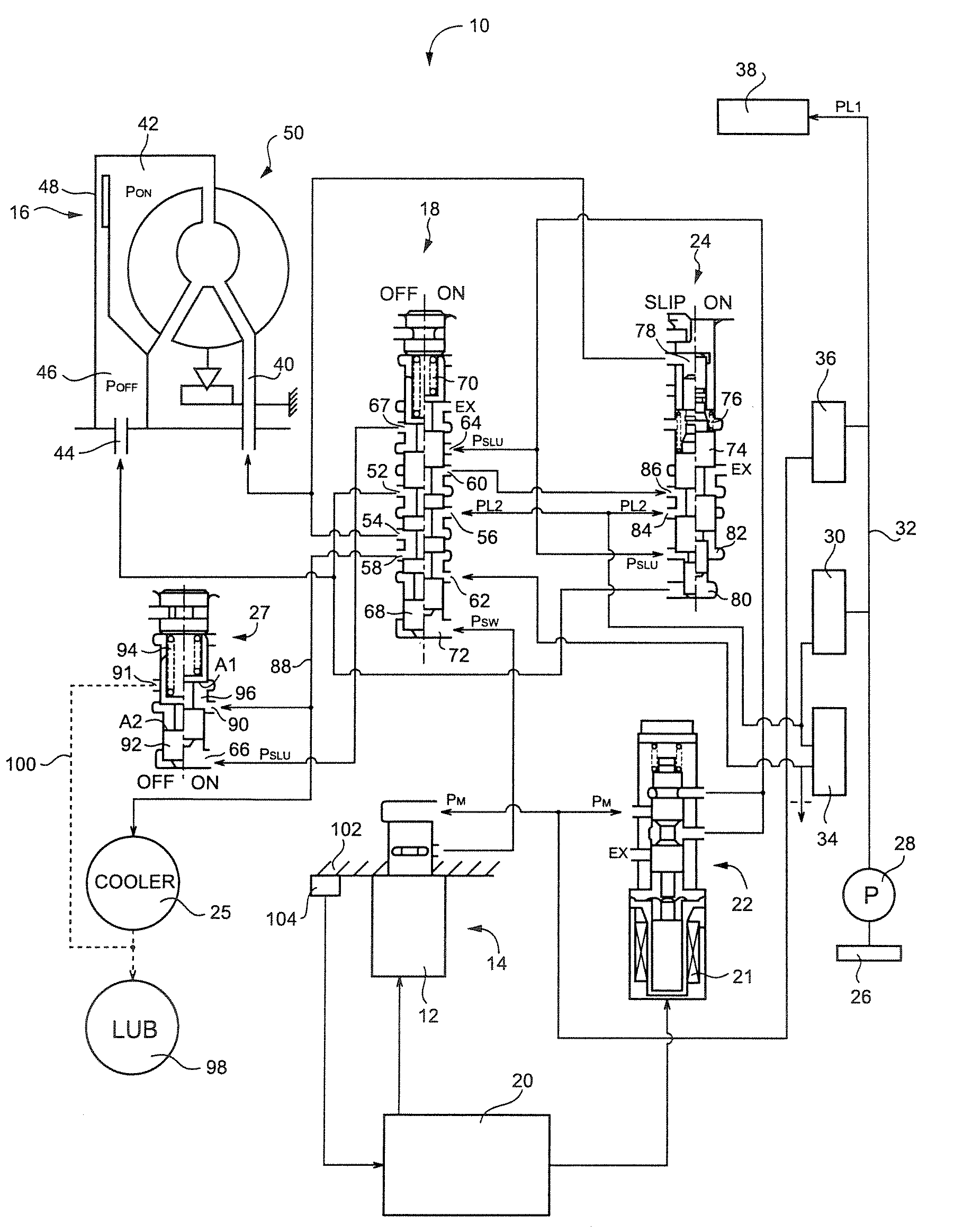
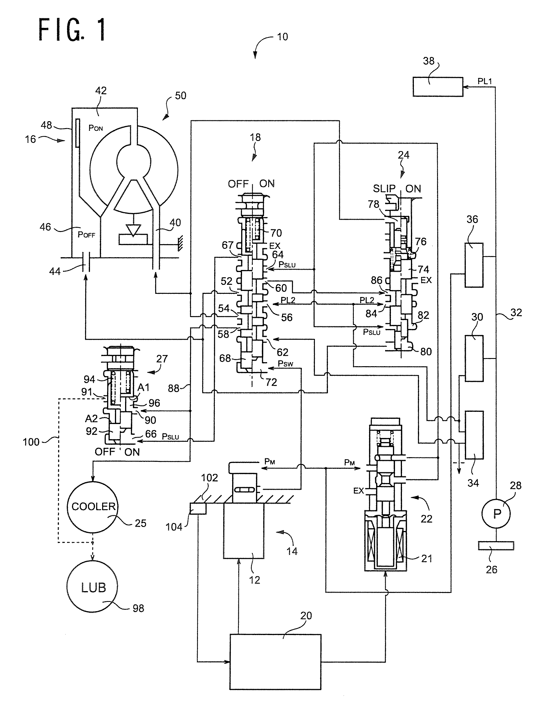
[0031]Referring first to FIG. 1, there are shown a hydraulic control circuit 10 and an electronic control device 20 which cooperate with each other to provide a hydraulic control apparatus constructed according to this invention, to control a vehicular fluid-actuated power transmitting device in the form of a torque converter 50 provided with a lock-up clutch 16. The torque converter 50 is disposed between an engine and an automatic transmission (not shown) of an automotive vehicle.
[0032]The hydraulic control circuit 10 includes: a solenoid-operated switching valve 14 provided with a switching solenoid 12 which is energized to generate a switching pilot pressure Psw; a clutch switching valve 18 operable according to the switching pilot pressure Psw, between a releasing position (OFF position) for placing the lock-up clutch 16 in its released state, and an engaging position (ON position) for placing the lock-up clutch 16 in its engaged state; a solenoid-operated slip control valve 22...
second embodiment
[0056]The hydraulic control circuit 110 is different from the hydraulic control circuit 10, only in that the hydraulic control circuit 110 further includes a solenoid-operated switching valve 112. In this second embodiment, the oil cooler by-pass valve 27 is controlled according to the switching pilot pressure PSW generated by the solenoid-operated switching valve 112 under the control of the electronic control device 20. The switching valve 112 has a solenoid energized and de-energized by the electric control device 20. When the solenoid 12 of the solenoid-operated switching valve 112 is in its de-energized or off state, the modulated pressure PM generated by the second supply portion 116 is not applied as the switching pilot pressure Psw from the switching valve 112 to the fluid chamber 66 of the oil cooler by-pass valve 27. When the same solenoid is in its energized or on state, the modulated pressure PM is applied as the switching pilot pressure PSW from the switching valve 112 ...
third embodiment
[0059]FIG. 4 shows a hydraulic control circuit 130 which cooperates with the electronic control device 20 (shown in FIG. 1 but not shown in FIG. 3) to provide a hydraulic control apparatus for the fluid-actuated power transmitting device in the form of the torque converter 50 provided with the lock-up clutch 16, which hydraulic control apparatus is constructed according to the present invention. In FIG. 3, the electronic control device 20, strainer 26, pressure regulating valves 30, 34, 36, etc. are not shown, but the hydraulic control circuit 130 includes the strainer, pressure regulating valves 30, 34, 36 and other hydraulic components shown in FIG. 1, and is controlled by the electronic control device 20.
[0060]The hydraulic control circuit 130 is different from the hydraulic control circuit 10, only in that the hydraulic control circuit 130 includes an oil cooler by-pass valve 132, which does not receive the pilot pressure PSLU from the solenoid-operated slip control valve 22 or ...
PUM
 Abstract
Description
Claims
Application Information
 - R&D
- Intellectual Property
- Life Sciences
- Materials
- Tech Scout
- Unparalleled Data Quality
- Higher Quality Content
- 60% Fewer Hallucinations
Browse by: Latest US Patents, China's latest patents, Technical Efficacy Thesaurus, Application Domain, Technology Topic, Popular Technical Reports.
© 2025 PatSnap. All rights reserved.Legal|Privacy policy|Modern Slavery Act Transparency Statement|Sitemap|About US| Contact US: help@patsnap.com


