Circular-shaped metal structure, method of fabricating the same, and apparatus for fabricating the same

a metal structure and circular shape technology, applied in the direction of manufacturing tools, applications, instruments, etc., can solve the problems of difficult or almost impossible to keep the thickness of the pipe wall constant, and achieve the effects of improving the thermal coefficient, high mechanical strength, and high elasticity

Active Publication Date: 2007-08-16
ENDO MFG COMPANY
View PDF17 Cites 5 Cited by
  • Summary
  • Abstract
  • Description
  • Claims
  • Application Information

AI Technical Summary

Benefits of technology

[0009] It is also an object of the present invention to further provide a method of fabricating the same, and an apparatus for fabricating the same both of which can keep a thickness of a wall constant, and further keep an outer diameter of a wall constant.
[0042] Most of conventional photosensitive drums are comprised of a big cylinder composed of aluminum. It would be possible to downsize a printer or copier by using the circular-shaped metal structure as a belt in place of such a conventional photosensitive drum. Furthermore, it would be possible in a color printer or copier to shorten a period of time in which a sheet passes a plurality of photosensitive drums associated with different colors such as red, green and blue, ensuring a high speed and reduction in a weight, and saving a space.

Problems solved by technology

However, the above-mentioned method is accompanied with a problem that it is quite difficult or almost impossible to keep a thickness of a wall of the pipe constant, and to accomplish a desired outer diameter of the pipe, because the pipe is lengthened in an axial direction by reducing a thickness of a wall of the pipe.

Method used


Image

  • Circular-shaped metal structure, method of fabricating the same, and apparatus for fabricating the same
  • Circular-shaped metal structure, method of fabricating the same, and apparatus for fabricating the same
  • Circular-shaped metal structure, method of fabricating the same, and apparatus for fabricating the same

Examples


Embodiment Construction

[0052] Preferred embodiments in accordance with the present invention will be explained hereinbelow with reference to drawings.

[0053] Hereinbelow is explained a method of fabricating a circular-shaped metal structure, in accordance with the embodiment. In the embodiment, it is assumed that a metal cylinder is fabricated as a circular-shaped metal structure in accordance with the method.

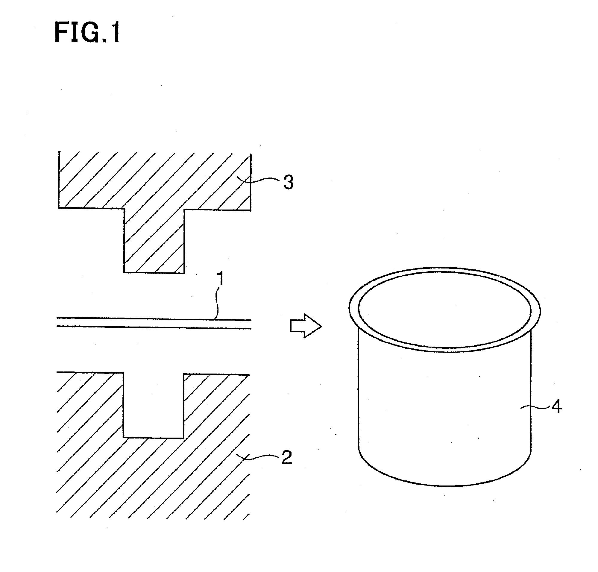
[0054] First, as illustrated in FIG. 1, a thin metal sheet 1 is placed between a female jig 2 and a punch 3 to fabricate a pipe 4 having a bottom. Deeper the pipe 4 is, more readily the pipe 4 can be spun. Hence, it is preferable that the pipe 4 is fabricated by warm drawing where the female jig 2 is heated and the punch 3 is cooled.

[0055] For instance, it is assumed that a SUS304 plate is pressed by warm and cold drawing. If a SUS304 plate is pressed at a room temperature, a critical drawing ratio, which is defined as a ratio of a diameter (A) of a cylindrical object to a diameter (B) of a punch (...


PUM

PropertyMeasurementUnit
Lengthaaaaaaaaaa
Fractionaaaaaaaaaa
Thicknessaaaaaaaaaa

Abstract

A method of fabricating a circular-shaped metal structure includes the steps of (a) rotating a pipe around an axis thereof, the pipe being composed of a plastic-workable metal, (b) moving a jig towards the pipe in a direction perpendicular to the axis until the jig makes contact with an outer surface of the pipe, and compressing the jig onto the pipe, (c) moving the jig in a direction in parallel with the axis with the jig being compressed onto the pipe while the pipe is kept rotated, (d) measuring a thickness of a wall of the pipe during the step (c), and (e) adjusting a pressure with which the jig is compressed onto the pipe, in accordance with the thickness measured in the step (d).

Description

CROSS REFERENCE TO RELATED APPLICATION [0001] This application is a continuation-in-part of U.S. application Ser. No. 10 / 391,862, filed Mar. 19, 2003, which application in turn claims priority from Japanese Application Serial No. 2002-81679 filed Mar. 22, 2002.BACKGROUND OF THE INVENTION [0002] 1. Field of the Invention [0003] The invention relates to a thin-walled circular-shaped metal structure and a method of fabricating the same, and more particularly to such a metal structure usable as a photosensitive drum or a fixing roller in an electrophotographic printer or copier, and a method of fabricating the same. [0004] 2. Description of the Related Art [0005] For instance, Japanese Patent Application Publication No. 2001-225134 has suggested a method of fabricating a circular-shaped metal structure, including the steps of rotating a pipe around an axis thereof, and compressing a jig onto an outer surface of the pipe while the pipe is kept in rotation. The pipe is composed of a plast...

Claims


Application Information

Patent Timeline
IPC IPC(8): B23Q17/00G03G15/20B21C37/06B21D22/14B21D22/16B21D51/10B21D53/14B21H1/00F16C13/00G03G5/10G03G15/00G03G21/00
CPCB21D22/16Y10T29/49764Y10T29/49998B21D53/14
Inventor ITO, YOUJI
Owner ENDO MFG COMPANY
Why Eureka
Try Eureka