
Reusable miniature camera head

a camera head and miniature technology, applied in the field of remote imaging, can solve the problems of high cost of rigid, semi-rigid and flexible endoscopes, inability to directly view the operating field of the person carrying out the procedure, and reuse for numerous procedures

Inactive Publication Date: 2007-08-09
MEDIGUS LTD
View PDF21 Cites 148 Cited by
  • Summary
  • Abstract
  • Description
  • Claims
  • Application Information

AI Technical Summary

Benefits of technology

[0023] In some embodiments of the camera head of the invention, circuitry is printed on the surface of one or more ceramic or polymer printed circuit boards (PCBs) and some or all of the components of the electronic driver are mounted on the PCBs. The electronic driver typically includes an amplifying c...

Problems solved by technology

Minimal access diagnostics and / or therapy, e.g. laparoscopy, interventional flexible endoscopy, minimal access surgery, and percutaneous interventional radiology, are generally carried out within the body cavities or small incisions in the abdomen and therefore the person carrying out the procedure cannot directly view the operating field.
The high cost of rigid, semi-rigid, and flexible endoscopes dictates that they must be reused for numerous procedures.
This in turn dictates that they must be sterilized between each procedure, which further increases the expense, since they must be built using special techniques and special materials to be able to withstand the harsh chemicals and / or high temperatures and / or washing machines of the sterilization and cleaning procedure.
As the size of the CCD sensor on which the camera is based becomes smaller, a number of technical and practical problems have become apparent to the inventors.
When the size of the CCD sensor becomes smaller than that disclosed in the above mentioned patent application, the size of the components of the electronic driver of the camera becomes the limiting factor that has to be overcome.
Additionally, from a practical point-of-view, the detachable camera heads become so small that it is difficult to handle them.

Method used


Image

  • Reusable miniature camera head
  • Reusable miniature camera head
  • Reusable miniature camera head

Examples


Embodiment Construction

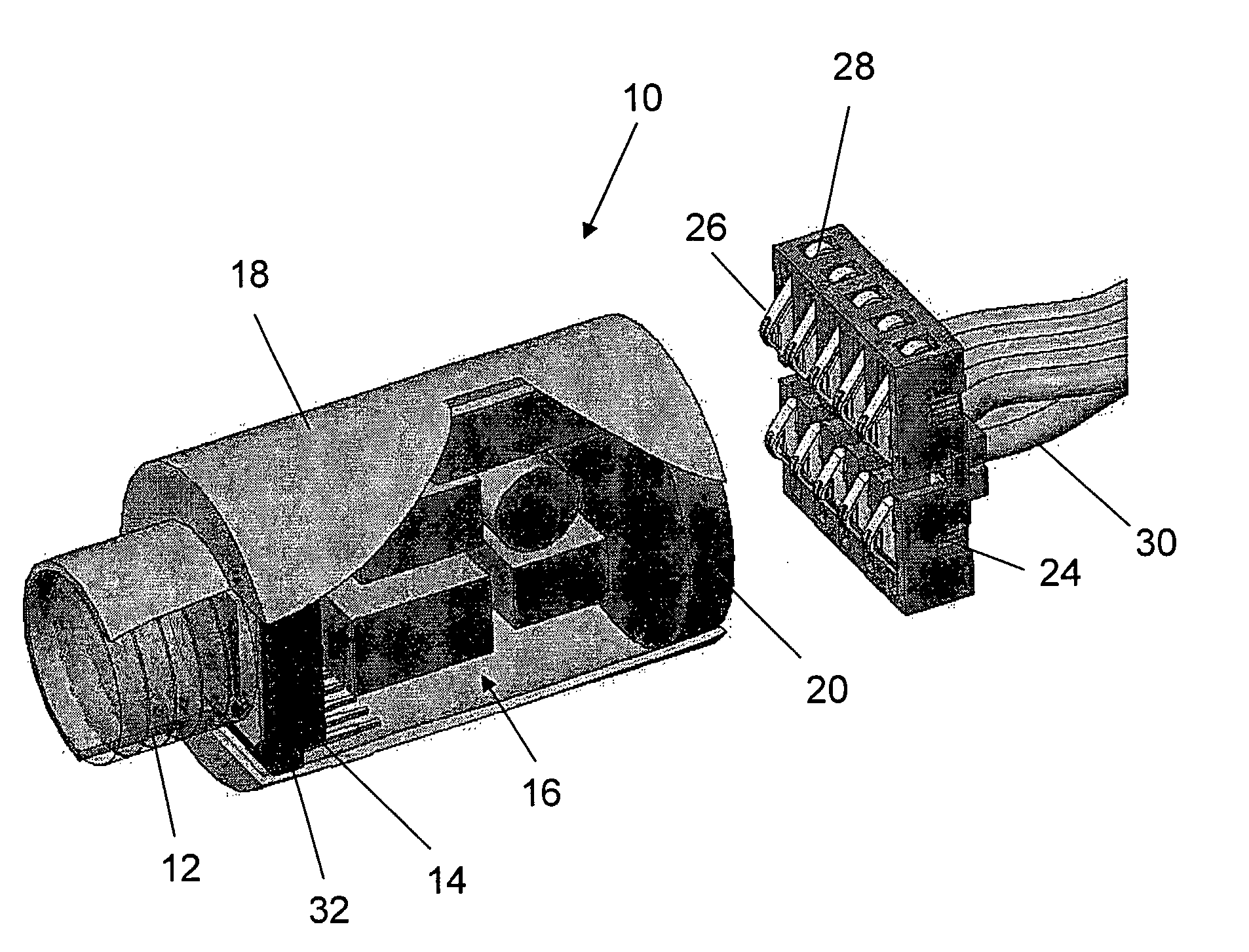
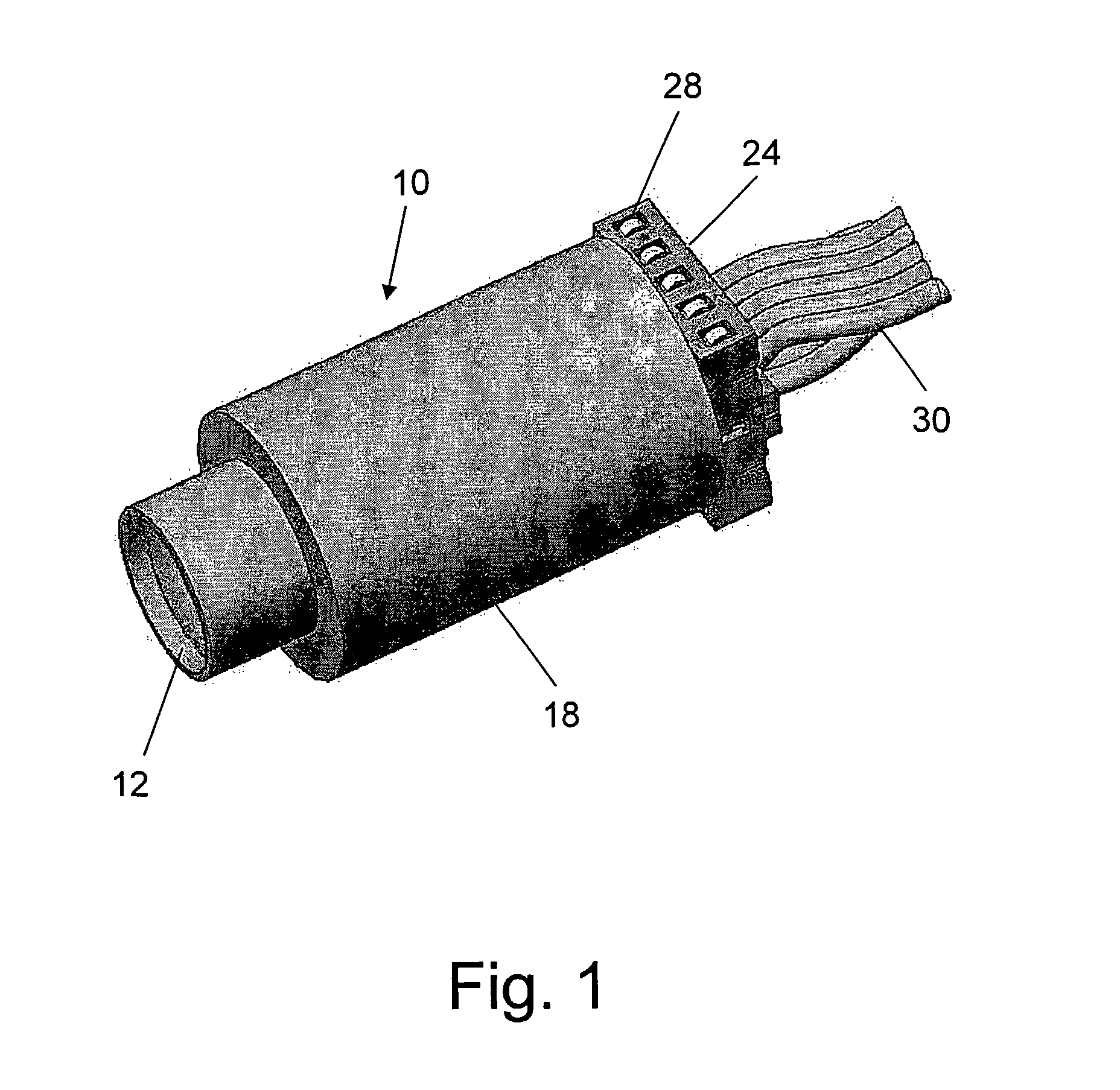
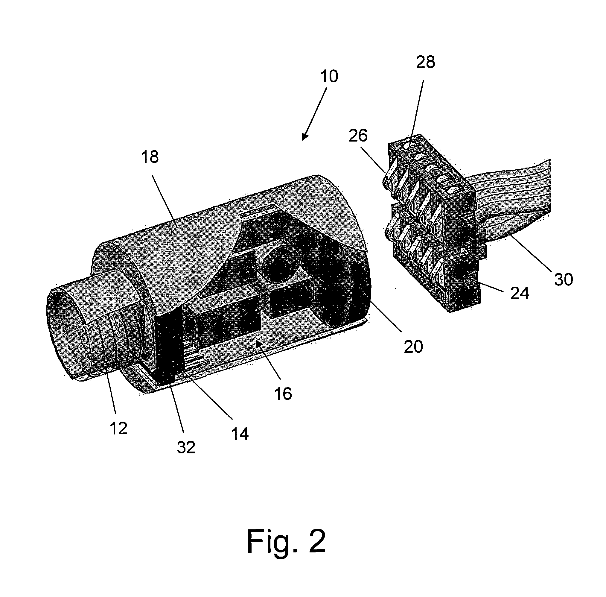
[0053] FIGS. 1 to 3 show a first embodiment of the reusable camera head 10 of the invention. Referring first to FIG. 1, camera head 10 is a closed housing 18, preferably cylindrically shaped, with a lens system 12 at its front end. The camera head 10 is shown in FIG. 1 attached to external electrical connector 24. External electrical connector 24 has around its outer perimeter clasps 28, which can be for example leaf springs, which are used to hold external electric connector in position in a socket at the distal end of the endoscope. Signal transmission and electric power supply wires 30 are attached to the back face of external electrical connector 24 and are in electrical contact with a plurality of pins 26 (see FIG. 2) arranged in a pattern on the front face of connector 24.

[0054]FIG. 2 and FIG. 3 show the camera head 10 with part of the housing 18 removed to reveal the interior of the camera head. The camera head 10 is shown disconnected from the external electrical connector ...


PUM


Abstract

The invention is a reusable miniature camera head (10) that can be attached to and detached from an object. The camera head comprises: a housing (18), a lens system (12), a solid-state sensor (14), components of an electronic driver (16), and an internal electrical connector (20) located at the proximal end of the housing and having a plurality of sockets (22) or pins (110) on its external face. The object has an external connector (24) for receiving the camera head. The internal and external electrical connectors comprise a plurality of pins or sockets arranged in matching patterns on opposing faces thereby allowing the camera head to be attached to or disconnected by engaging the two connectors. In preferred embodiments of the invention, the object to which the camera head is attached is an endoscopic or laparoscopic device, the solid-state sensor is a Charge Coupled Device (CCD), and the housing does not contain a printed circuit board.

Description

FIELD OF THE INVENTION [0001] The present invention relates to the field of remote imaging. Particularly the invention relates to a reusable miniature camera head that can be attached to and detached from an object. BACKGROUND OF THE INVENTION [0002] Minimal access diagnostics and / or therapy, e.g. laparoscopy, interventional flexible endoscopy, minimal access surgery, and percutaneous interventional radiology, are generally carried out within the body cavities or small incisions in the abdomen and therefore the person carrying out the procedure cannot directly view the operating field. For this reason, the ability to carry out such procedures is dependent on the imaging systems that display the images obtained by the camera sensor focused on the scene. [0003] The imaging systems comprise a miniature camera head based on solid-state sensors, e.g. Charge Coupled Device (CCD) and permanently attached to the distal tip of the rigid, semi-rigid, or flexible endoscope and connected, usual...

Claims


Application Information

Patent Timeline
IPC IPC(8): H04N5/225A61B1/00A61B1/04A61B1/05G02B23/24
CPCA61B1/00124A61B1/042A61B1/051H04N2005/2255G02B23/2423G02B23/2484H04N5/2251A61B1/053H04N23/50H04N23/555G02B23/24A61B1/05H04N23/00
Inventor SONNENSCHEIN, ELAZARSONNENSCHEIN, MINELUGOVRIN, AMIRSHEINBERG, SHAI
Owner MEDIGUS LTD
Learn More