
Data processor

a data processor and high-performance technology, applied in the field of high-performance data processors, can solve the problems of overhead resulting from branch execution, code size enlarge, instruction lengthening, etc., and achieve the effect of reducing branch penalty and excellent code efficiency

Inactive Publication Date: 2007-07-26
RENESAS TECH CORP
View PDF9 Cites 8 Cited by
  • Summary
  • Abstract
  • Description
  • Claims
  • Application Information

AI Technical Summary

Benefits of technology

The solution enables efficient condition execution with reduced branch penalty and code size, improving performance and power efficiency by allowing conditional execution based on flag information, enabling complex conditional processing without increasing instruction length.

Problems solved by technology

As one of large factors hindering performance improvement in the pipeline processing, there is overhead resulting from execution of a branch.
When making setting to perform condition execution in all instructions, however, fields specifying execution conditions are required for all instructions and hence the instruction length lengthens.
Thus, when comprising condition specify fields for all instructions, there has been such a problem that the code size enlarges.
Further, there have been such problems that it is difficult to implement sophisticated parallel processing of a superscalar, VLIW and the like used in the processor, while an external interrupt immediately after the XC instruction is also limited.
There has been such a problem that, when forcibly suppressing the instruction length, the number of instructions encodable to short instructions reduces and the code size enlarges similarly to the processor ARM.
However, there has been such another problem that, only one condition can be determined with these instructions and hence complex expressions cannot be efficiently processed when a composite condition of a plurality of condition is specified or the like.

Method used


Image

  • Data processor
  • Data processor
  • Data processor

Examples


embodiment 1

[0115]

[0116] Now, a data processor of an embodiment 1 of the present invention will be discussed. The data processor of this embodiment is a 16-bit processor and processes addresses and data of 16 bits.

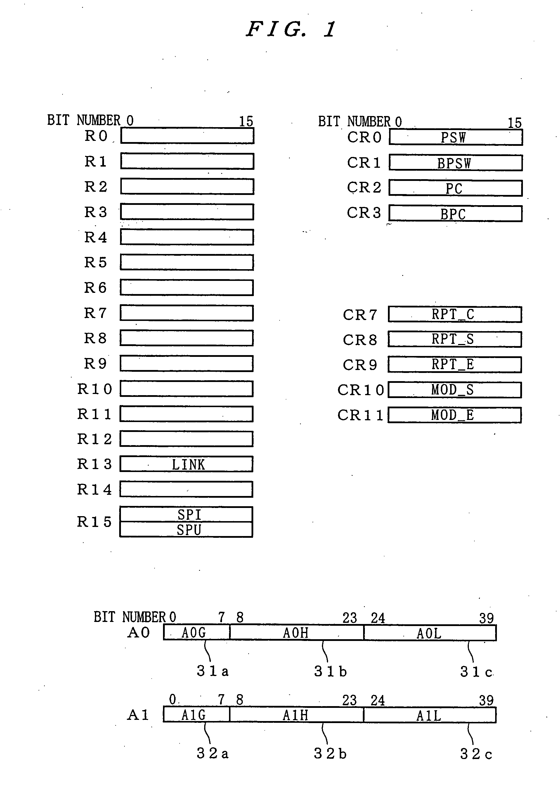
[0117]FIG. 1 illustrates a register set of the data processor of this embodiment. The data processor adopts Big Endian on the order of bit or byte, and the most significant bit (MSB) corresponds to the bit 0.

[0118] Sixteen general-purpose registers R0 to R15 each store data or address value. The registers R0 to R14 are general-purpose registers and the register R13 is designated as a LINK register to store a return address in execution of sub-routine jump instruction. The register R15 is a stack pointer SP, and a stack pointer SPI for interrupt and a stack pointer SPU for user which are switched over to each other by a processor status word PSW as discussed later. Hereafter, the stack pointers SPI and SPU are generally termed a stack pointer SP.

[0119] Except specific cases, 4-bit r...

embodiment 2

[0260] A data processor according to an embodiment 2 of the present invention is now described. The basic structure is identical to the data processor of the embodiment 1. In the data processor of the embodiment 2, a point comprising three flags which can be referred to as an execution condition is different from the data processor of the embodiment 1. Description is now made while noting the difference between the same and the embodiment 1 of the present invention.

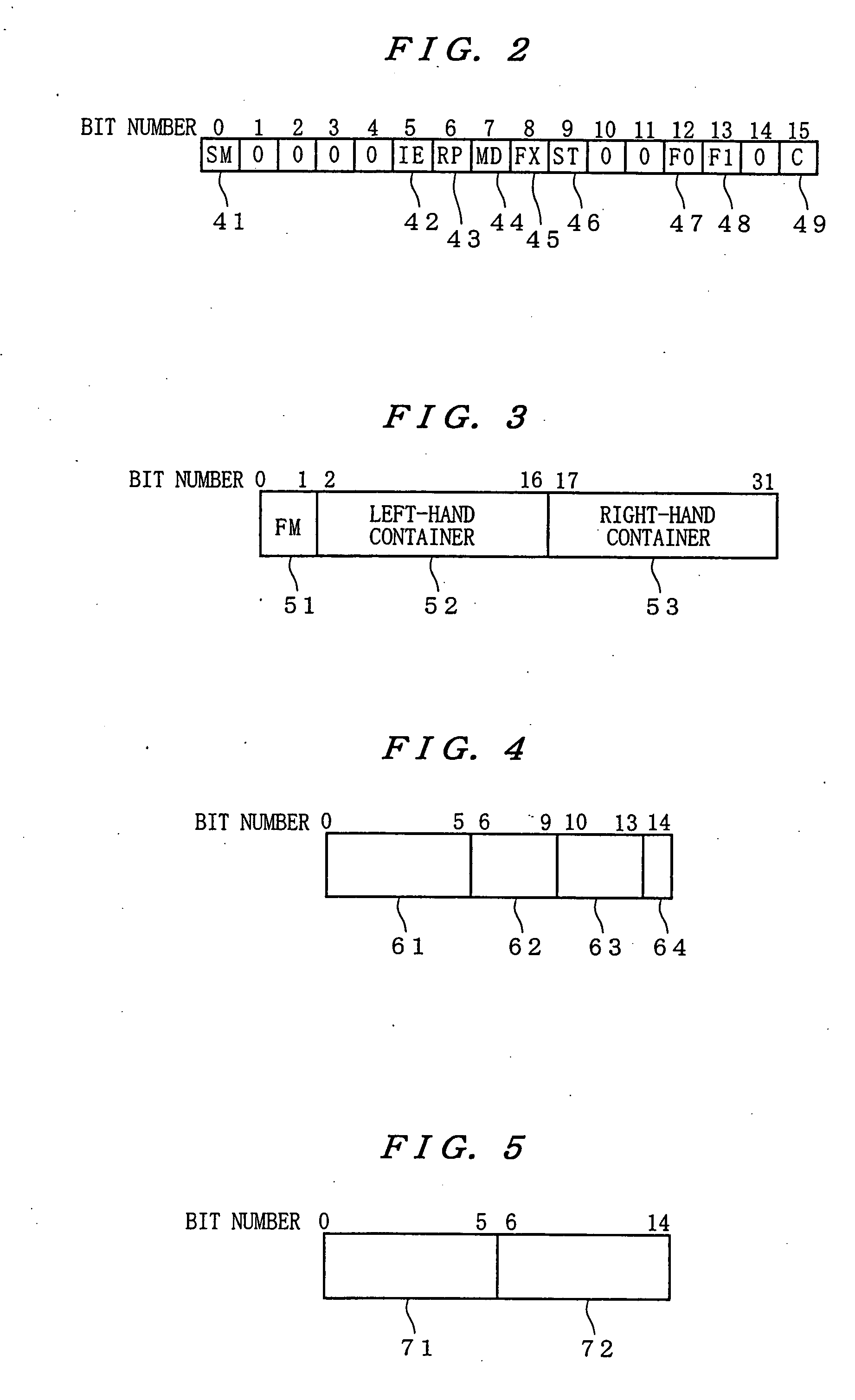
[0261]FIG. 34 shows a processor status word (PSW) of the data processor of the embodiment 2. In the data processor of the embodiment 2, three flags of an F0 flag 47, an F1 flag 48 and an F2 flag 50 are updated in a comparison instruction or the like, and referred to as an execution condition. The point that the F2 flag 50 of bit 14 is added is different from the data processor of the embodiment 1, and allocation of the remaining bits is identical.

[0262]FIG. 35 shows instruction bit allocation of an execution condition s...

embodiment 3

[0270] While the case of unconditionally performing updating of three flags in comparison instruction processing has been shown in the embodiment 2, it may comprise two types of instructions of an instruction updating the flags other than the F0 flag 47 and an instruction not performing updating when updating the flags in the comparison instruction. As an example, FIG. 39 shows bit allocation of a comparison instruction of a short format. In a CMP instruction, it updates only the F0 flag 47 depending on an operation result, and in a CMPX instruction, it updates the F0, F1 and F2 flags 47, 48 and 50. The CMP instruction and the CMPX instruction are distinguished by “0” / “1” of an F field 752.

[0271] The basic structure is substantially identical to the data processor (FIG. 27, FIG. 38) of the embodiment 2. As elements, processing contents of a first decoder 112 (123), a second decoder 114 (124) and a flag update control unit 521 are different.

[0272] A flag update control unit (corres...


PUM


Abstract

A data processor, and particularly in a data processor performing condition execution on the basis of flag information, aims at obtaining a data processor having excellent code efficiency, which can reduce branch penalty. In order to attain the aforementioned object, it is so structured that, when a first instruction decoded in a first decoder is an execution condition specifying instruction specifying the execution condition for a pair of second instructions executed in parallel, a first execution condition determination unit performs determination of the execution condition for the second instructions defined by the execution condition specifying instruction on the basis of the flag information and controls assertion / non-assertion of an execution inhibit signal on the basis of whether the execution condition defined by the execution condition specifying instruction is satisfied or not.

Description

CROSS REFERENCE TO RELATED APPLICATIONS [0001] This application is a divisional application of application Ser. No. 10 / 285,646, filed Nov. 1, 2002, which is a divisional application of application Ser. No. 09 / 355,024, filed Jul. 23, 1999, now U.S. Pat. No. 6,484,253, issued Nov. 19, 2002, which is a 371 of International Application PCT / JP97 / 00173, filed Jan. 24, 1997.TECHNICAL FIELD [0002] The present invention relates to a data processor of high performance, and more particularly, it relates to a data processor performing condition execution on the basis of a flag on which an operation result is reflected. BACKGROUND TECHNIQUE [0003] In a data processor, pipeline processing is frequently employed for improving the performance. As one of large factors hindering performance improvement in the pipeline processing, there is overhead resulting from execution of a branch. While various contrivances are made as to this, there is condition execution of an instruction as one thereof. [0004]...

Claims


Application Information

Patent Timeline
Patent Type & Authority Applications(United States)
IPC IPC(8): G06F9/44G06F9/32G06F9/38
CPCG06F9/30036G06F9/3838G06F9/30072G06F9/30094G06F9/30101G06F9/30163G06F9/30167G06F9/321G06F9/322G06F9/325G06F9/3804G06F9/3822G06F9/3842G06F9/3863G06F9/3885G06F9/3857G06F9/30014G06F9/3013G06F9/3859G06F9/30058G06F9/38585G06F9/3858G06F9/3854G06F9/323
Inventor MATSUO, MASAHITO
Owner RENESAS TECH CORP
Learn More