
Capillary column and method of making

a technology of capillaries and columns, applied in the field of capillaries, can solve the problems of time-consuming, fused silica capillaries, and inability to produce identical surface characteristics after being subjected to the same deactivation treatment, and achieve the effect of rapid and simple method of making

Inactive Publication Date: 2007-07-26
MALIK ABDUL +1
View PDF38 Cites 28 Cited by
  • Summary
  • Abstract
  • Description
  • Claims
  • Application Information

AI Technical Summary

Benefits of technology

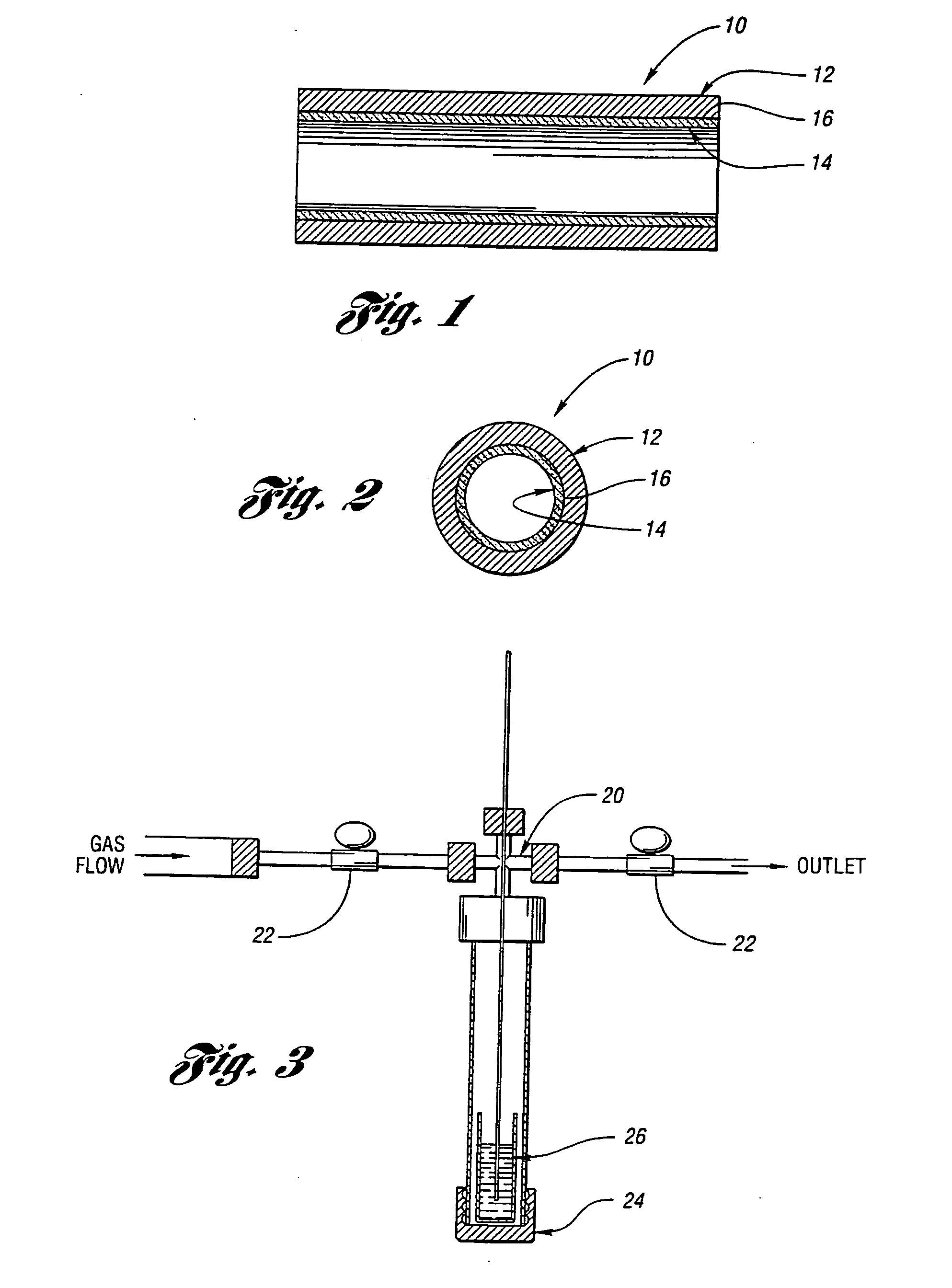
[0013] The present invention provides a new and useful capillary column and a rapid and simple method of making such a column.
[0014] One aspect of the present invention is a new and useful capillary column for use, e.g. in gas chromatography. The capillary column comprises a tube structure, and a deactivated surface-bonded sol-gel coating on a portion of the tube structure to form a stationary phase coating on that portion of the tube structure. According to the present invention the deactivated stationary-phase sol-gel coating enables separation of analytes while minimizing adsorption of analytes on the sol-gel coated tube structure.
[0038] Additionally, in the preferred form of the present invention, the tube structure is hydrothermally pretreated before the portion of the tube structure is reacted with the sol-gel solution. This technique generally improves the performance of the sol-gel coated tube structure, and is particularly useful with relatively long tube structures (e.g. longer than about 10 m.).
[0039] In this context a principal object of this invention has been to develop a rapid and simple method for simultaneous deactivation, coating, and stationary phase immobilization in GC. To achieve this goal, a sol-gel chemistry-based approach to column preparation is provided that is a viable alternative to conventional GC column technology. The sol-gel column technology eliminates the major drawbacks of conventional column technology through chemical bonding of the stationary phase molecules to an interfacial organic-inorganic polymer layer that evolves on the top of the original capillary surface. This provides a quick and efficient method for the fabrication of high efficiency columns with enhanced thermal stability.

Problems solved by technology

Capillary GC is now a matured separation technique that is widely used in various fields of science and industry.2-5 Contemporary technology for the preparation of open tubular columns, is however, time-consuming.
Moreover, different degrees of reaction and adsorption activities are shown by different types of surface silanol groups.14 As a result, fused silica capillaries from different batches (or even from the same batch but stored and / or handled under different conditions), may not produce identical surface characteristics after being subjected to the same deactivation treatments.
This makes surface deactivation a difficult to reproduce procedure.
To overcome these difficulties, some researchers have used hydrothermal surface treatments to standardize silanol group concentrations and their distributions over the surface.15 However, this additional step makes the lengthy column making procedure even longer.
Static coating is another time-consuming step in conventional column technology.
First, the technique is excessively time consuming, and not very suitable for automation.
Second, the physically coated stationary phase film shows a pronounced tendency to rearrangements that may ultimately result in droplet formation due to Rayleigh instability.18 Such a structural change in the coated films may serve as a cause for the deterioration or even complete loss of the column's separation capability.
First, polar stationary phases are difficult to immobilize by this technique.20 Second, free radical cross-linking reactions are difficult to control to ensure the same degree of cross-linking in different columns with the same stationary phase.
Third, cross-linking reactions may lead to significant changes in the polymer structure, and chromatographic properties of the resulting immobilized polymer may significantly differ from those of the originally taken stationary phase.9 All these drawbacks add up to make column preparation by conventional techniques a difficult-to-control and reproduce task.21

Method used


Image

  • Capillary column and method of making
  • Capillary column and method of making
  • Capillary column and method of making

Examples


Embodiment Construction

[0081] As described above, the present invention is directed to a capillary column and to a method of making the capillary column. A capillary column constructed according to the present invention is particularly useful in gas chromatography, and is also intended to be useful in forming capillary columns for liquid chromatography, capillary electrochromatography, and supercritical fluid chromatography. Moreover, a capillary column constructed according to the present invention is intended to be useful in providing sample preconcentration, where an analyte sample has a relatively small concentration of a compound of interest, and there is a need for preconcentration of the sample to perform subsequent analysis.

[0082] The present invention is described below in connection with the formation of a capillary column intended for use in gas chromatography.

[0083] Most generally, the present invention provides a rapid and simple method for simultaneous deactivation, coating, and stationary...


PUM


Abstract

The present invention concerns a new and useful structure for forming a capillary tube, e.g. for gas chromatography, and methods for forming the capillary tube are described. The capillary tube comprises a tube structure, and a deactivated surface-bonded sol-gel coating on a surface of the tube structure to form a stationary phase coating on that surface of the tube structure. According to the present invention the deactivated stationary phase sol-gel coating enables separation of analytes while minimizing adsorption of analytes on the separation column structure.

Description

CROSS-REFERENCE TO RELATED APPLICATIONS [0001] This application is a continuation of U.S. patent application Ser. No. 09 / 763,419, filed Jul. 19, 2001; which is a National Stage filing of International Application No. PCT / US99 / 19113, filed Aug. 20, 1999; which claims priority to U.S. Provisional Application No. 60 / 102,483, filed Sep. 30, 1998 and U.S. Provisional Application No. 60 / 097,382, filed Aug. 21, 1998.TECHNICAL FIELD [0002] The present invention relates to a new and useful capillary column, e.g. for gas chromatography, and to a new and useful method of making such a capillary tube. INTRODUCTION [0003] The introduction of an open tubular column by Golan1 about three decades ago, has revolutionized the analytical capability of gas chromatography (GC). Capillary GC is now a matured separation technique that is widely used in various fields of science and industry.2-5 Contemporary technology for the preparation of open tubular columns, is however, time-consuming. It consists of ...

Claims


Application Information

Patent Timeline
IPC IPC(8): G01N30/02G01N30/56G01N30/60
CPCB01J2220/86G01N30/56G01N2030/567G01N2030/025G01N30/6073
Inventor MALIK, ABDULWANG, DONGXIN
Owner MALIK ABDUL
Learn More