Resonant switching power source apparatus
a power source and switching technology, applied in the direction of electric variable regulation, process and machine control, instruments, etc., can solve problems such as restricting charging, and achieve the effect of preventing the breakage of switching elements
- Summary
- Abstract
- Description
- Claims
- Application Information
AI Technical Summary
Benefits of technology
Problems solved by technology
Method used
Image


Examples
first embodiment
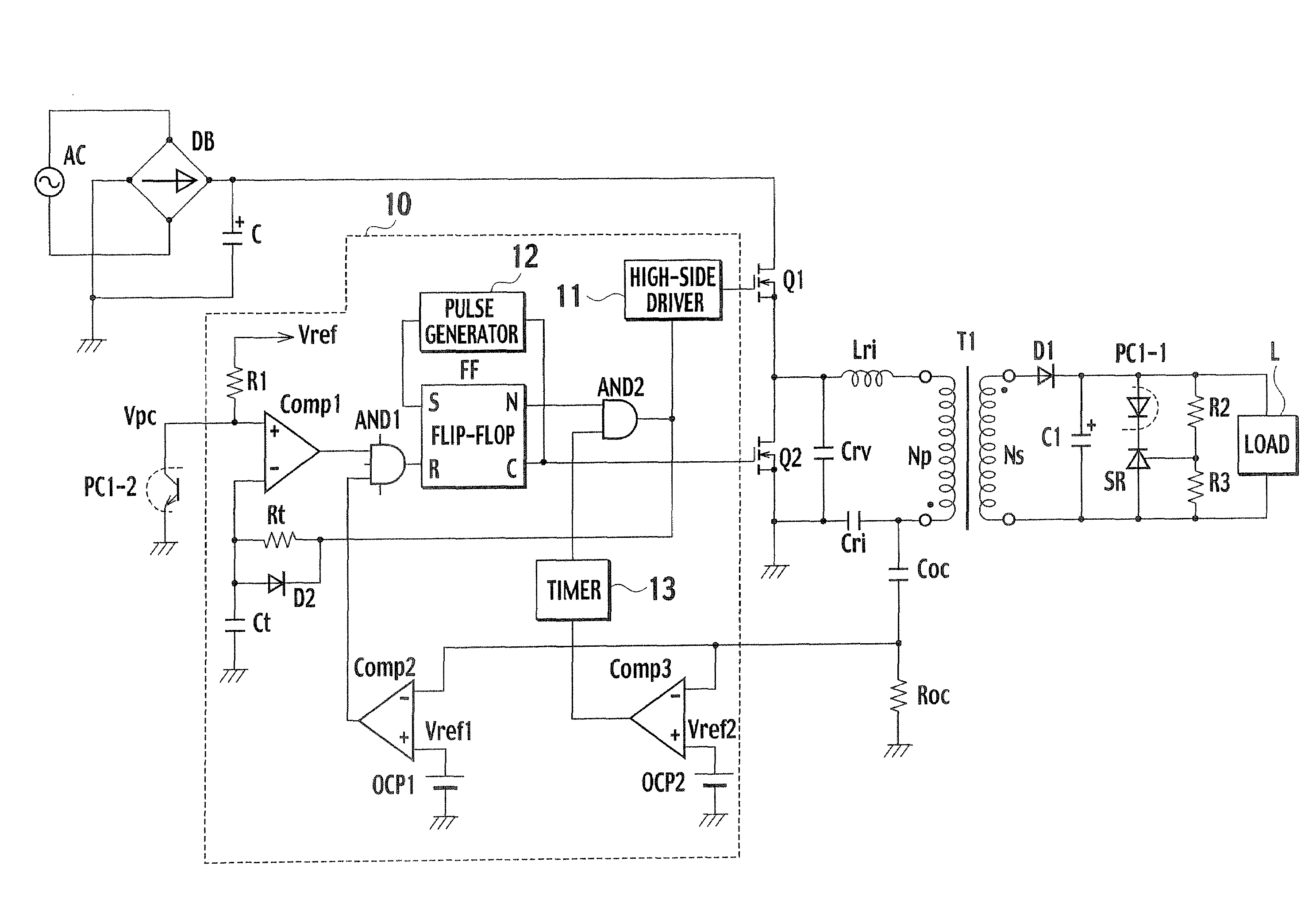
[0042]FIG. 4 is a circuit diagram showing a resonant switching power source apparatus according to the first embodiment of the present invention. In addition to the controller 110 of the resonant switching power source apparatus of the related art shown in FIG. 1, a controller 10 of the resonant switching power source apparatus of the first embodiment includes an AND gate AND2, a timer 13, a comparator Comp3, and a reference power source OCP2.
[0043]According to the first embodiment of the present invention, a first overcurrent detector includes a capacitor Coc, a resistor Roc, a comparator Comp2, and a reference power source OCP1. A first overcurrent protector includes an AND gate AND1. A second overcurrent detector includes the capacitor Coc, the resistor Roc, the comparator Comp3, and the reference power source OCP2. A second overcurrent protector includes the timer 13 and the AND gate AND2.
[0044]Among parts shown in FIG. 4 those that are the same as those of the related art of FI...
second embodiment
[0052]FIG. 6 is a circuit diagram showing a resonant switching power source apparatus according to the second embodiment of the present invention. This embodiment is based on the first embodiment shown in FIG. 4, and therefore, the same parts as those of the first embodiment are represented with the same reference marks to omit or simplify their explanations. Compared with the first embodiment, the second embodiment additionally has a current detection resistor Roc 2 between the source of the second switching element Q2 and the ground and the inverting input terminal (−) of the comparator Comp3 is connected to a connection point between the source of the second switching element Q2 and the resistor Roc2.
[0053]FIG. 7 shows operational waveforms of the second embodiment. As explained above, an output voltage of the power source apparatus is low at the start of the apparatus, and therefore, an excitation current of the primary winding Np is not reset within an ON period of the second s...
third embodiment
[0056]A resonant switching power source apparatus according to the third embodiment of the present invention employs a soft start circuit to suppress a current increase at the start of the apparatus, thereby preventing an excessive current from passing to the first and second switching elements Q1 and Q2.
[0057]FIG. 8 is a circuit diagram showing the resonant switching power source apparatus according to the third embodiment. This embodiment is based on the first embodiment shown in FIG. 4, and therefore, the same parts as those of the first embodiment are represented with the same reference marks to omit or simplify their explanations. The third embodiment removes the reference power source OCP1 from the first embodiment and employs the soft start circuit including a resistor R4, a resistor R5, a capacitor C3, and a diode D3. The soft start circuit supplies a voltage divided by the resistors R4 and R5 instead of the reference voltage Vref1 of the first embodiment.
[0058]The resistors...
PUM
 Abstract
Description
Claims
Application Information
 - R&D
- Intellectual Property
- Life Sciences
- Materials
- Tech Scout
- Unparalleled Data Quality
- Higher Quality Content
- 60% Fewer Hallucinations
Browse by: Latest US Patents, China's latest patents, Technical Efficacy Thesaurus, Application Domain, Technology Topic, Popular Technical Reports.
© 2025 PatSnap. All rights reserved.Legal|Privacy policy|Modern Slavery Act Transparency Statement|Sitemap|About US| Contact US: help@patsnap.com