
Aircraft shock strut and improved bearings therefor

a technology for aircraft shock struts and bearings, which is applied in the direction of shock absorbers, mechanical devices, transportation and packaging, etc., can solve the problems of gears that are especially susceptible to stiction, take a significant change in force, and limited rate of motion

Inactive Publication Date: 2007-07-19
THE BF GOODRICH CO
View PDF14 Cites 17 Cited by
  • Summary
  • Abstract
  • Description
  • Claims
  • Application Information

AI Technical Summary

Benefits of technology

[0006] The present invention provides an aircraft shock strut wherein sliding engagement between the cylinder and piston is effected through use of one or more lead-free polytetrafluoroethylene (PTFE) bearing surfaces. Use of bearings having lead-free PTFE bearing surfaces allows for minimization of stick-slip without discoloration of the hydraulic fluid within the shock strut.
[0009] According to another aspect of the invention, there is provided a method of preventing stick-slip in an aircraft landing gear including at least one shock strut, the at least one shock strut including a cylinder and a piston telescopically movable within the cylinder. The method comprises mounting a first bearing to one of the cylinder and the piston, where the first bearing has a first bearing surface formed by a lead-free polytetrafluoroethylene (PTFE) layer for providing sliding engagement with the other of the cylinder and the piston.

Problems solved by technology

Shock struts also dissipate energy by passing the oil through the orifice so that as the shock absorber is compressed or extended, its rate of motion is limited by the damping action from the interaction of the orifice and the oil.
This problem occurs when a shock strut reaches static equilibrium, stops stroking, and takes a significant change in force before the shock strut strokes again.
Landing gears that are especially susceptible to stiction are those whose geometry causes high bearing loads under static conditions.
While use of leaded bearing surfaces aids in reducing stiction problems, the leaded bearing assemblies are problematic in that, as the bearing wears, it releases particles of lead within the hydraulic fluid, which cause the fluid to darken.
Darkening of hydraulic fluid is problematic because it causes confusion as to the condition of the shock strut during inspections by equipment maintenance personnel.

Method used


Image

  • Aircraft shock strut and improved bearings therefor
  • Aircraft shock strut and improved bearings therefor
  • Aircraft shock strut and improved bearings therefor

Examples


Embodiment Construction

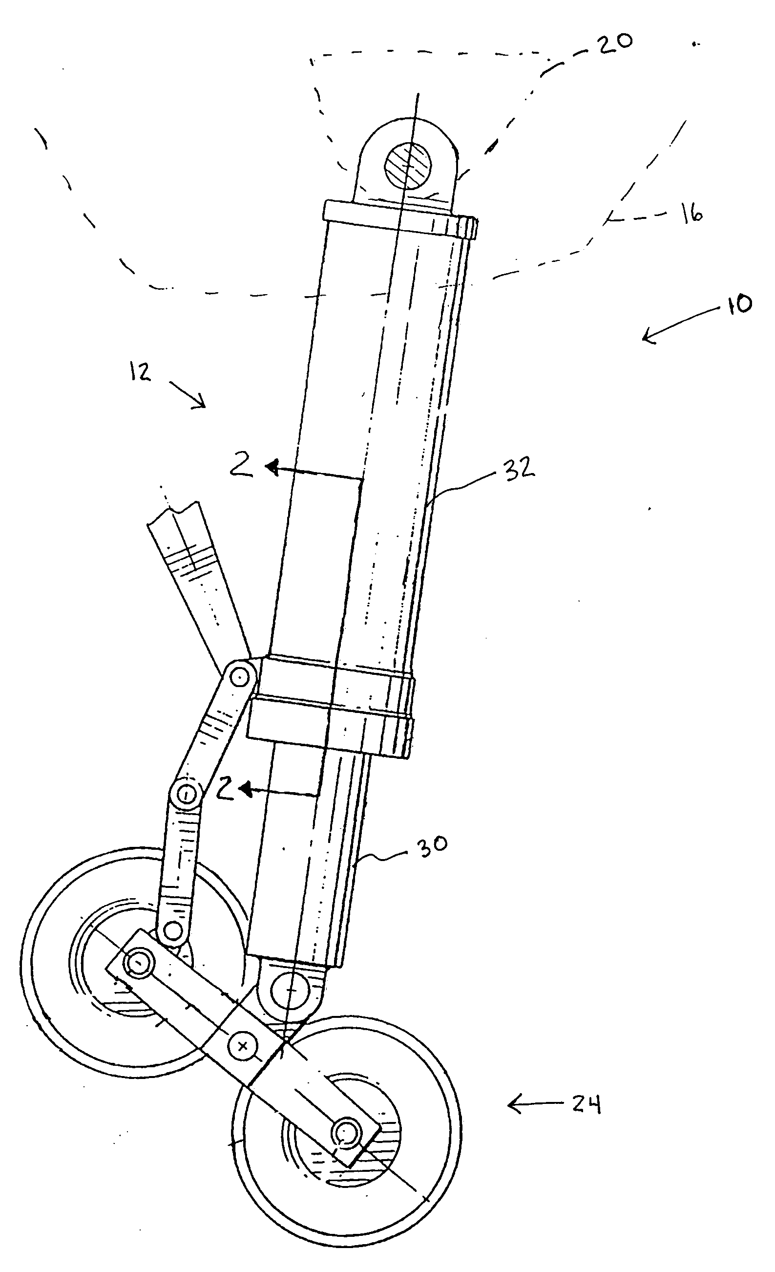
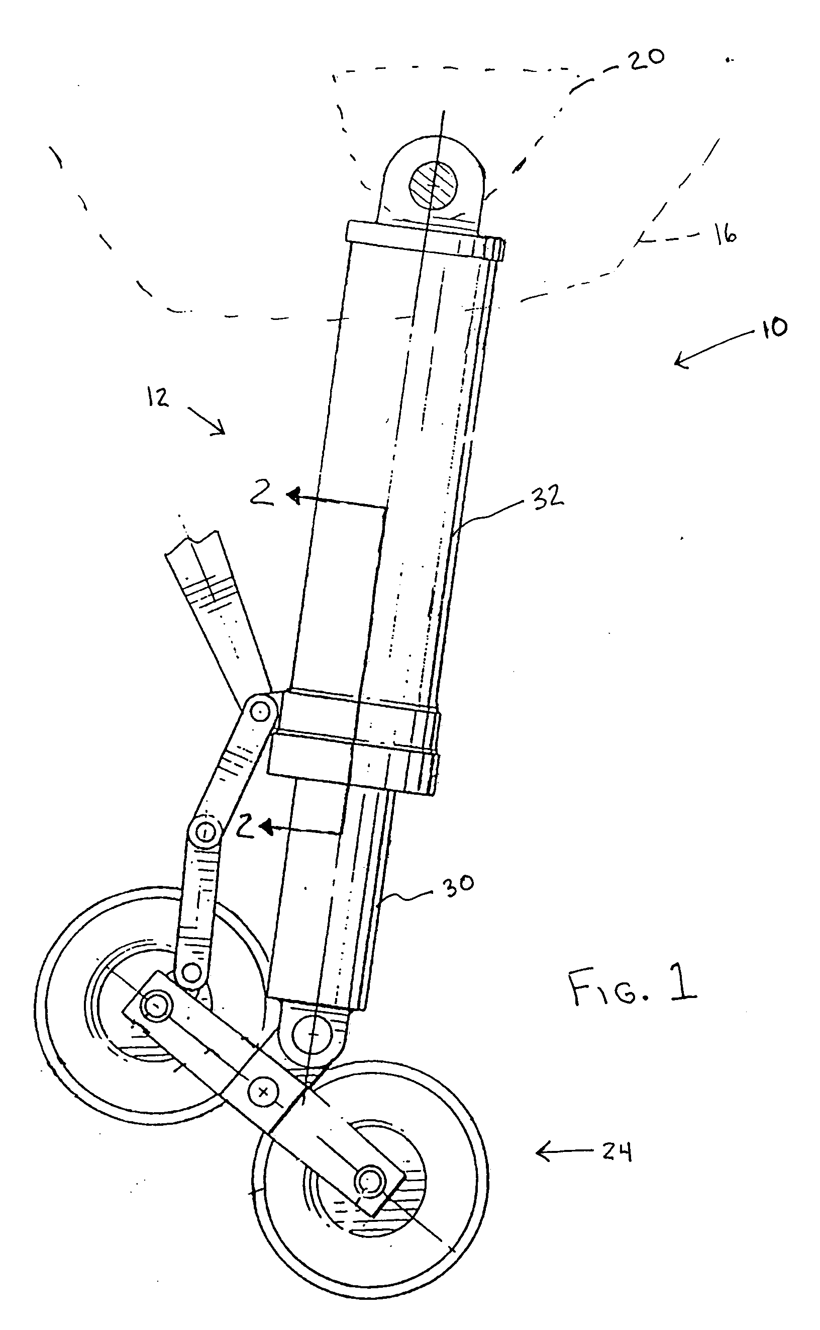
[0024]FIG. 1 presents a simplified aircraft landing gear assembly 10, including an exemplary aircraft shock strut 12, shown mounted at an upper end to an aircraft structure 16 by an attachment member 20. The references herein to a shock strut or an aircraft shock strut refer to shock struts employed in aircraft landing gear. The lower end of the shock strut 12 is attached to a wheel assembly 24. The aircraft structure 16, attachment member 20 and wheel assembly 24 are shown in simple or outline form, while other structures such as locking mechanisms and retracting mechanisms are not shown in FIG. 1 in order to avoid obscuring the shock strut. Various arrangements of such structures are known in the art and are not critical to the description or understanding of the invention.

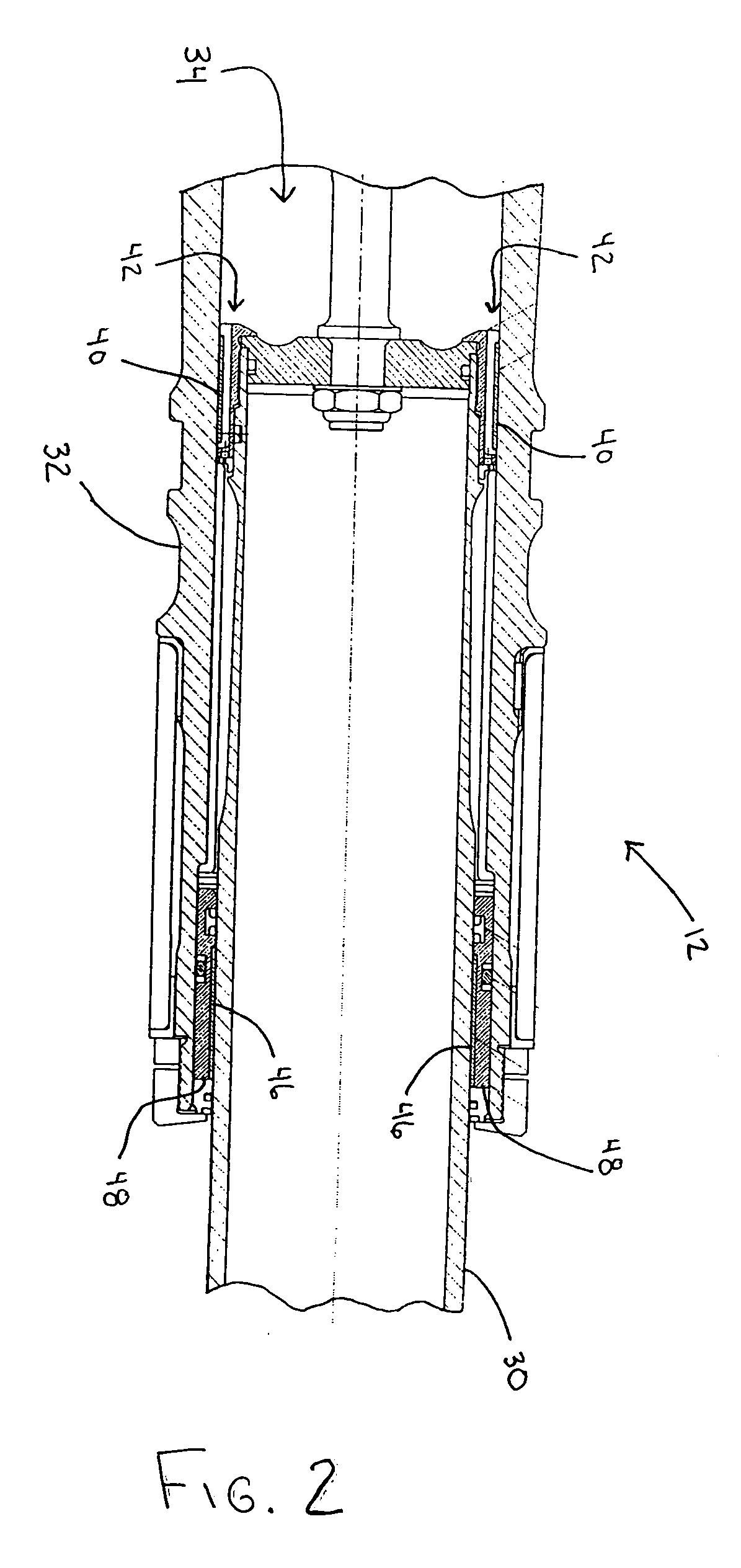
[0025] The shock strut 12 includes a piston 30 and a cylinder 32, which may be cylindrical as is customary, or some other shape, if desired. The shock strut is configured for attachment to the aircraft structur...


PUM

PropertyMeasurementUnit
Fractionaaaaaaaaaa
Fractionaaaaaaaaaa
Percent by volumeaaaaaaaaaa

Abstract

An aircraft shock strut includes a cylinder and a piston telescopically movable within the cylinder. A first bearing is mounted to one of the cylinder and the piston. The first bearing includes a support structure and a first bearing surface formed by a lead-free PTFE material layer for providing sliding engagement with the other of the cylinder and the piston.

Description

FIELD OF THE INVENTION [0001] The present invention relates to aircraft shock struts for absorbing and damping shock forces, such as during landing, taxiing or takeoff, and particularly improved bearings for an aircraft shock strut. BACKGROUND OF THE INVENTION [0002] Shock absorbing devices are used in a wide variety of vehicle suspension systems for controlling motion of the vehicle and its tires with respect to the ground and for reducing transmission of transient forces from the ground to the vehicle. Shock absorbing struts are a common and necessary component in most aircraft landing gear assemblies. The shock struts used in the landing gear of aircraft generally are subject to more demanding performance requirements than most if not all ground vehicle shock absorbers. In particular, shock struts must control motion of the landing gear, and absorb and damp loads imposed on the gear during landing, taxiing and takeoff. [0003] A shock strut generally accomplishes these functions b...

Claims


Application Information

Patent Timeline
IPC IPC(8): B64C25/00F16F7/00
CPCB64C25/60F16C33/206Y02T10/865F16C29/02F16C2326/43F16C2208/02F16C2208/52F16C2208/32
Inventor LUCE, WILLIAM E.
Owner THE BF GOODRICH CO
Learn More