
Method and device for calculating bit error rate of received signal

a bit error rate and received signal technology, applied in error detection/correction, instruments, coding, etc., can solve the problems of multi-path fading, complex task of optimal decoding of turbo codes, and need for mechanisms, so as to reduce the load on the receiver, reduce the complexity of the circuit, and reduce the effect of memory limitation

Inactive Publication Date: 2007-07-12
UNWIRED PLANET
View PDF0 Cites 76 Cited by
  • Summary
  • Abstract
  • Description
  • Claims
  • Application Information

AI Technical Summary

Benefits of technology

[0024] It is a still further object of the present invention to provide systems and methods performing improved estimates of bit error rate with low computational load and which provide such estimates over a range of error rates, especially over low signal to noise ratios.
[0030] The present invention provides for systems and methods for determining estimates of bit error rate by utilizing look-up tables and which result in low circuit complexity and reduced load for the receiver. This is particularly beneficial for a mobile type receiver, such as a mobile terminal, which must often operate for extended periods on battery power and which contains limited memory.

Problems solved by technology

As the electromagnetic signal travels from the transmitting antenna to the receiving antenna, it encounters a transmission channel that is subject to reflections on different stationary and non-stationary objects resulting in so-called multi-path fading, by noise due to a variety of factors, for example background noise, noise introduced through transmitter and receiver components, noise introduced through atmospheric transmission conditions, and interference introduced from other transmitters operating on interfering carrier frequencies.
Furthermore, if errors are detected, a mechanism is needed to obtain the correct information.
Optimal decoding of turbo codes is often a very complex task, and may require large periods of time not usually available for on-line decoding.
Despite the use of error detection and correction techniques, the quality of the channel can nonetheless be such that some of the received information bits are erroneous, even after error correction has been performed by the receiver.
At or above a particular level however, the bit error rate becomes unacceptable because the amount of audio distortion makes the received speech difficult to understand.
However, in a cell based mobile communication system, increasing signal strength in one cell will result in increased interference in the adjacent cells resulting in an increased BER in those cells.
One problem, however, is that this scheme gives very poor performance at low C / N ratios.
However, since there is no guarantee that the channel decoder always corrects an erroneous bit as well as it may also change a correct bit into an incorrect bit, the re-encoding of this possibly partially corrected signal with the uncorrected signal will result in an erroneously calculated BER.
Hence, it is not always possible to implement the modified re-encode- and compare scheme.
Another drawback is that the modified re-encode- and compare scheme skips frames that fail the CRC.
There may not be sufficient frames left over in one measurement period to estimate the channel's BER.
In such case, it is necessary to increase the measurement period and / or the number of frames, which is not always possible.

Method used


Image

  • Method and device for calculating bit error rate of received signal
  • Method and device for calculating bit error rate of received signal
  • Method and device for calculating bit error rate of received signal

Examples


Embodiment Construction

[0032] The present invention will now be described more fully hereinafter with reference to the accompanying figure, in which the preferred embodiment of the invention is shown.

[0033] The Bit Error Rate (BER) calculation method and system of the present invention is used in a digital communication system and more precisely in the receiver station of the digital communication system.

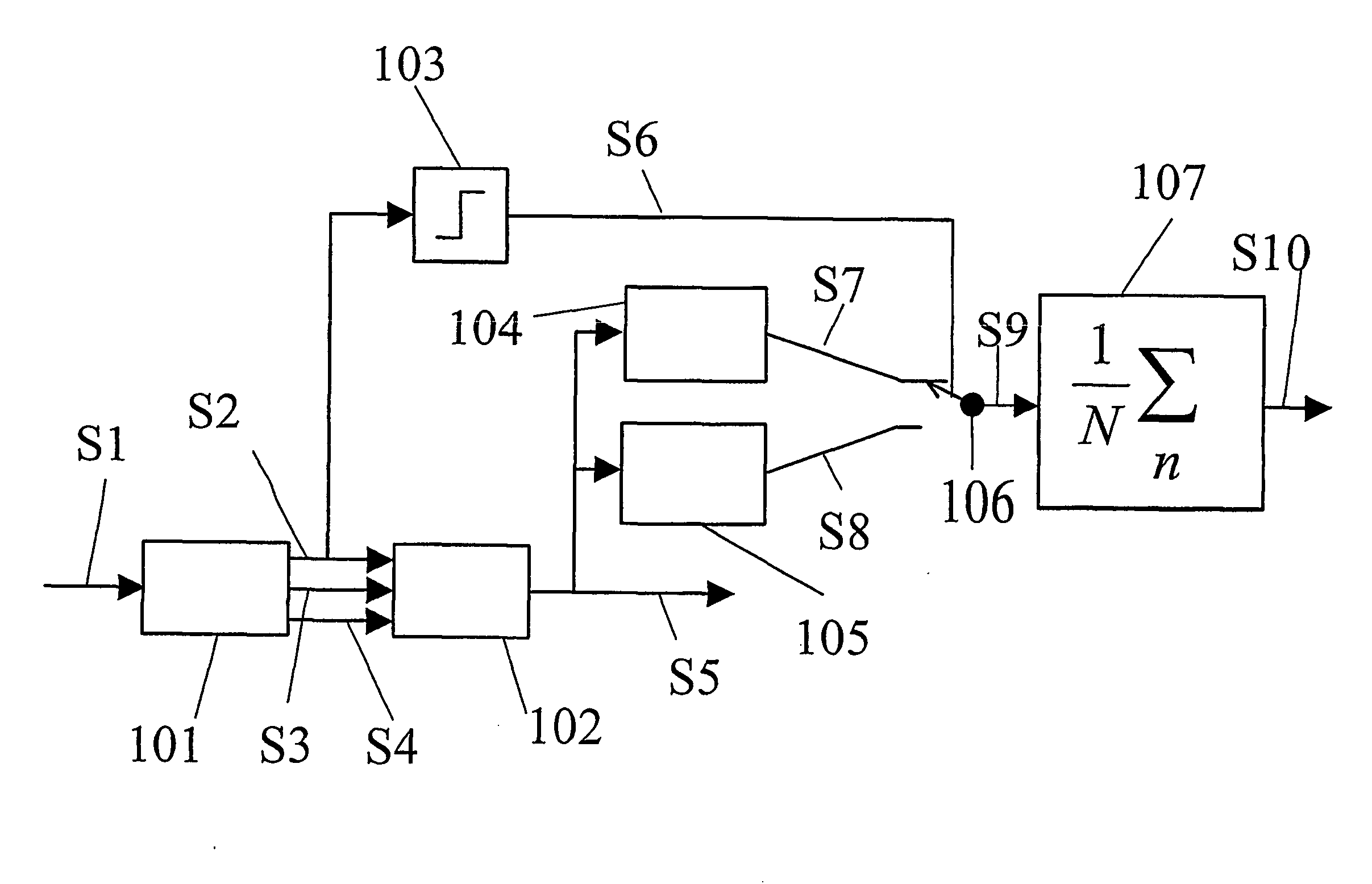
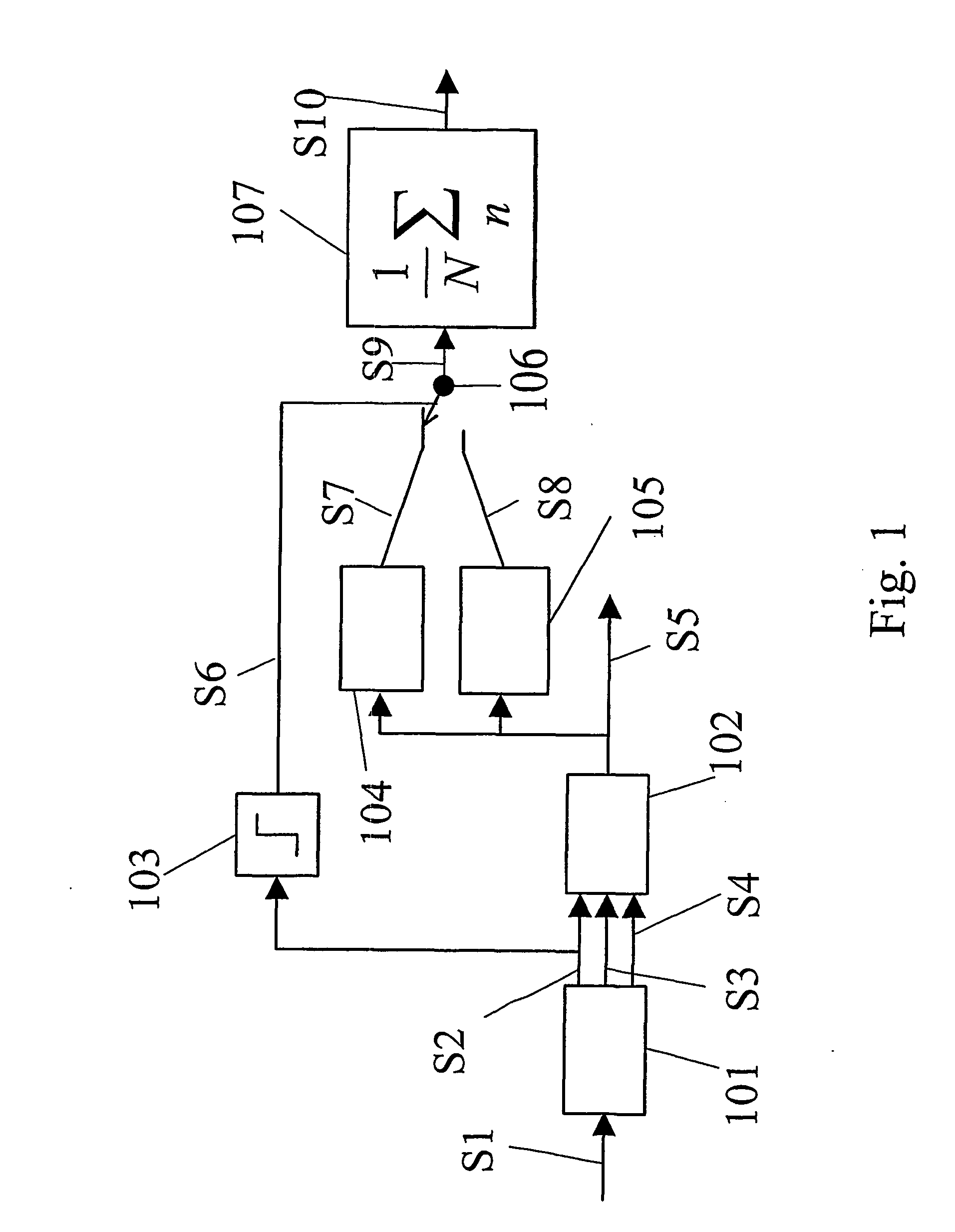
[0034] As known by those persons skilled in the art, the receiving station includes a receiver (not shown), demodulator (not shown), demultiplexer 101 and a decoder 102. The demodulator (not shown) produces a data stream consisting of soft bits S1. The demultiplexer splits this stream into the soft systematic input S2 and one or more soft parity inputs S3, S4. Streams S2, S3 and S4 are input to the decoder 102.

[0035] The decoder 102, upon receiving a complete data block, processes the inputs and produces soft-output S5 representing the likelihood of a received bit in the data frame being a logical 1 or...


PUM


Abstract

System and method of estimating radio channel bit error rate (BER) in a digital radio telecommunications system wherein the soft output of the turbo decoder is used as pointer or index to look-up-tables containing the bit-wise BER of a certain bit in the data field of the received frame. A quantizer quantizes the received data frame and the quantized bit operates on a switch which selects the appropriate look-up-table. By means of accumulation and scaling the average BER of a certain amount of bits are calculated. Decoding bit-errors may occur but as they are submitted to posterior probability estimation, systematic errors which normally happen at low SNR are avoided.

Description

TECHNICAL FIELD OF THE INVENTION [0001] This invention relates to radio telecommunication systems and, more particularly, to a system and method of estimating radio channel bit error rate in a digital radio telecommunications system. BACKGROUND OF THE INVENTION [0002] The propagation of an electromagnetic signal from sender to receiver is affected by the imperfections of the transmission channel. As the electromagnetic signal travels from the transmitting antenna to the receiving antenna, it encounters a transmission channel that is subject to reflections on different stationary and non-stationary objects resulting in so-called multi-path fading, by noise due to a variety of factors, for example background noise, noise introduced through transmitter and receiver components, noise introduced through atmospheric transmission conditions, and interference introduced from other transmitters operating on interfering carrier frequencies. [0003] As a result of this imperfect transmission ch...

Claims


Application Information

Patent Timeline
Patent Type & Authority Applications(United States)
IPC IPC(8): G06F11/00H04L1/20
CPCH04L1/20
Inventor MOELKER, DIGNUS-JAN
Owner UNWIRED PLANET
Learn More