Method of and apparatus for producing sub-critical water decomposition products

a technology of sub-critical water and decomposition products, which is applied in the direction of water, sludge treatment by oxidation, supercritical condition processes, etc., can solve the problems of reducing process efficiency, waste decomposition into carbon dioxide and water, and reducing process efficiency, so as to reduce equipment costs, reduce equipment costs, and control the decomposition reaction of the material to be processed

Inactive Publication Date: 2007-07-12
PUBLIC UNIVERSITY CORPORATION OSAKA CITY UNIVERSITY
View PDF13 Cites 12 Cited by
  • Summary
  • Abstract
  • Description
  • Claims
  • Application Information

AI Technical Summary

Benefits of technology

[0047] The method of producing sub-critical water decomposition products and the apparatus for sub-critical water decomposition treatment according to the present invention make it possible to freely set the reaction time for solid matter and the reaction time for solubilized material separately by adjusting the residence time of a sub-critical water dissolution part in the reactor. As a result, the decomposition reaction of the material to be processed can be controlled easily. Moreover, the method of producing sub-critical water decomposition products and the apparatus for sub-critical water decomposition treatment according to the present invention are capable of continuously processing material to be processed and are therefore suitable for large-scale operations. Furthermore, sub-critical conditions allow reactions to proceed more gently than supercritical conditions, making it possible to reduce equipment costs. Adjusting the residence time of the sub-critical water dissolution part makes it possible to produce desired useful substances selectively at high yield rates.

Problems solved by technology

In this method, however, the decomposition reaction is difficult to control.
If the reaction takes place excessively, the waste will be decomposed into carbon dioxide and water and useful substances cannot be recovered.
Conversely, if decomposition is insufficient, a large amount of residue will remain, degrading the process efficiency.
It is believed that the reason why the decomposition reaction is difficult to control with this method is that the hydrolysis reaction with sub-critical water proceeds on the surface of the solid components of the waste.
This method employs, however, a batch-type reaction and is therefore not suitable for large-scale operations.
Moreover, a problem is that the pores in the sintered filters tend to be plugged by various reaction products.
Nevertheless, because organic wastes that contain solid matter with a high water content has a density close to that of supercritical water, this method is problematic when decomposition reactions need to be controlled or when a specific decomposition product needs to be obtained at a high yield rate.
Moreover, this method requires a complicated apparatus configuration since supercritical water and organic waste material are pressure-fed through different charging ports to the fluidized bed; for the pressure-feeding, at least two high-pressure pressure-feeding apparatuses (compressing means), which are expensive, are necessary.
Furthermore, the material for the reactor needs to be resistant to corrosiveness of supercritical water, and therefore, it is necessary to use expensive materials such as Hastelloy and Inconel as the material for the reactor.
This increases the equipment costs.
Nevertheless, even with this method, it is difficult to control the decomposition of organic waste material.

Method used


Image

  • Method of and apparatus for producing sub-critical water decomposition products
  • Method of and apparatus for producing sub-critical water decomposition products
  • Method of and apparatus for producing sub-critical water decomposition products

Examples


embodiment 1

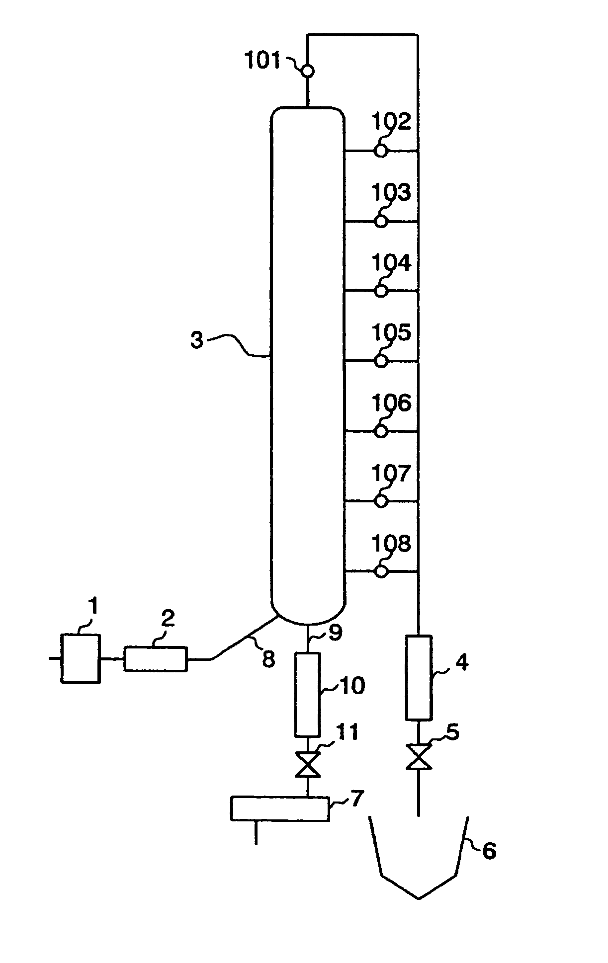
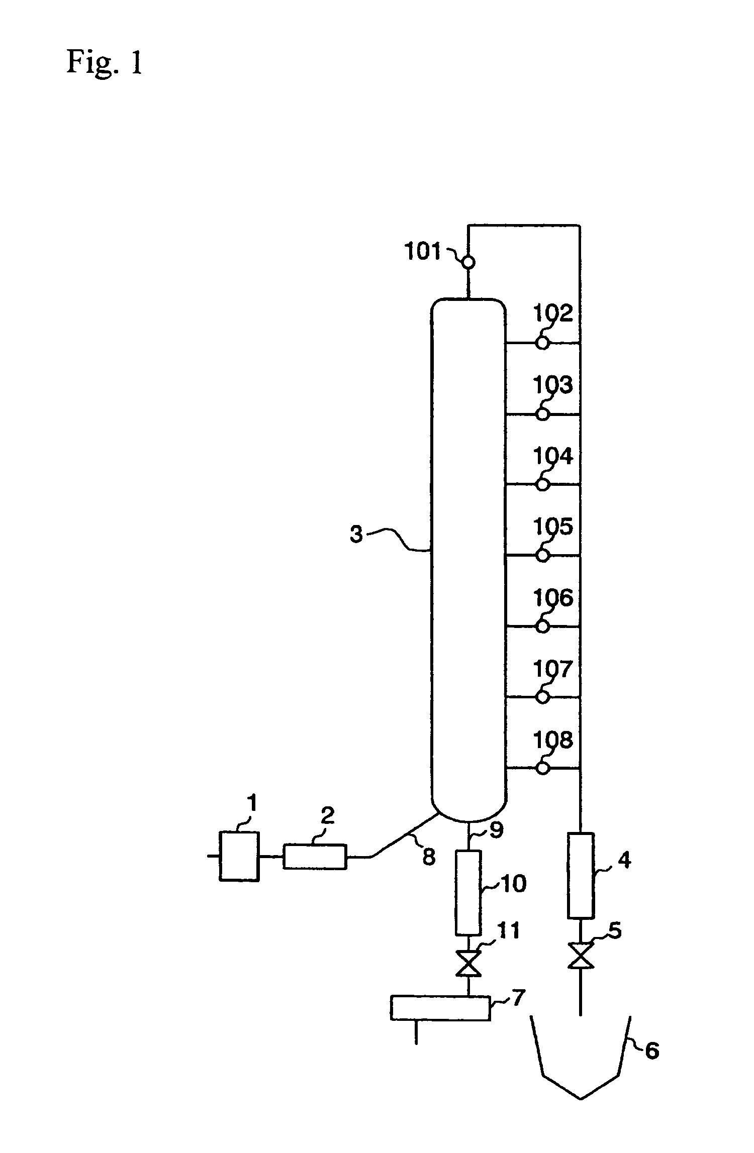
[0057]FIG. 1 is a schematic block diagram illustrating one example of the reaction apparatus according to Embodiment 1 of the present invention. As illustrated in this figure, this apparatus comprises a reactor 3, a compressing means 1, a heating means 2, a cooling pipe 4, a back-pressure valve 5, a reaction-completed-product recovery tank 6, and an effluent recovery tank 7. In the apparatus of FIG. 1, the compressing means 1 also serves as a mixture introducing means at the same time. The reactor 3 is of vertical type and in cylindrical tubular form, and is arranged substantially vertically. An inlet 8 and a discharge outlet 9 are provided at a bottom portion of the reactor 3. The compressing means 1 and the heating means 2 are connected to the just-mentioned inlet 8 by a piping. The inlet 8 is connected to the effluent recovery tank 7 via the cooling pipe and a back-pressure valve 11. The reactor 3 is provided with outlets on its head portion and its sidewall. In the example shown...

embodiment 2

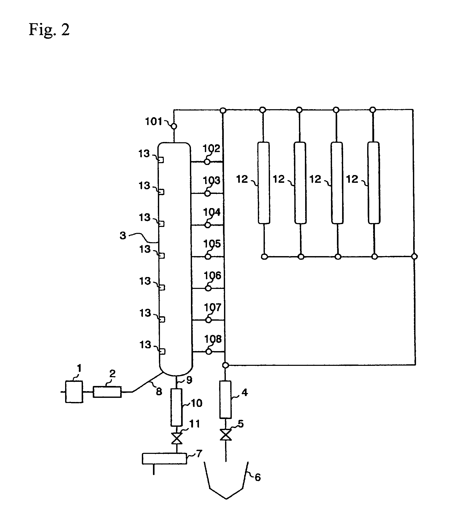
[0085] In Embodiment 2, the reaction apparatus of Embodiment 1 is further provided with reactors for secondary reaction. FIG. 2 is a schematic block diagram for illustrating another embodiment of the apparatus for sub-critical water decomposition product according to the present invention. In FIG. 2, the same parts as those in FIG. 1 are designated by the same reference numerals. As illustrated in FIG. 2, the 12 are connected to the outlet 101 of the reactor 3 via pipes. The reactors for secondary reaction 12 are connected to one another via pipes. Each of the pipes are provided with a switching valve. The reactors for secondary reaction 12 can be freely connected either in series or in parallel with one another by switching with the valves. These reactors for secondary reaction 12 are connected to a cooling pipe by a pipe and further connected to a back-pressure valve 5. A reaction-completed-product recovery tank 6 is disposed following the back-pressure valve 5. In the example sho...

embodiment 3

[0095]FIG. 3 is a schematic block diagram for illustrating another example of the apparatus for sub-critical water decomposition treatment according to the present invention. In FIG. 3, the same parts as those shown in FIG. 1 are designated by the same reference numerals. As illustrated in FIG. 3, the apparatus of the present embodiment is provided with an outlet that is continuously movable along the flow direction of the sub-critical water in the reactor 3.

[0096] The movable outlet comprises a flexible pipe 14, an intake port 15 that is arranged at the fore-end of the flexible pipe 14, for taking in a desired sub-critical water dissolution part, a chain 16 for hanging the flexible pipe 14, and an intra-bath wheel 17 that is capable of winding up or reeling out the chain 16. By adjusting the length of the chain 16, the intake port 15 can be fixed to a desired position.

[0097] In the example shown in this figure, the flexible pipe 14 is configured to be inserted from the top end of...


PUM

PropertyMeasurementUnit
temperatureaaaaaaaaaa
pore diameteraaaaaaaaaa
pressureaaaaaaaaaa

Abstract

[Problems] A method of and an apparatus for continuous sub-critical water decomposition treatment for material to be processed containing solid matter are provided, which are capable of controlling decomposition reaction of the material to be processed and suitable for large-scale operations. The method and the apparatus are also capable of minimizing equipment costs and selectively producing desired useful substances at high yield rates. [Means to Solve the Problems] Material to be processed is grinded in advance into particles, which are mixed with water to prepare slurry. The slurry is sent to a compressing means (1) through a pipe and is compressed. Next, the compressed slurry is sent to a heating means 2 and heated, and is brought into a sub-critical state. The slurry in a sub-critical condition is introduced through an inlet (8) into a bottom part of a reactor (3). In the reactor (3) a fixed bed, a fluidized bed, and a sub-critical water dissolution part are formed in that order from the bottom. One(s) of outlets (101) to 106 provided at top and side portions of the reactor 3 is / are selected so that the sub-critical water dissolution part is taken out therethrough, whereby the residence time of the sub-critical water is adjusted and thus the reaction time of sub-critical water decomposition of the material to be processed is adjusted.

Description

TECHNICAL FIELD OF THE INVENTION [0001] The present invention relates to methods of producing sub-critical water decomposition products, and apparatus for producing sub-critical water decomposition products. BACKGROUND ART [0002] The use of sub-critical / supercritical water decomposition reactions has been known as a method for recovering useful substances from wastes such as food wastes and wood wastes. For example, there has been a method in which cellulose, starch, and the like contained in a large amount in biomass are subjected to decomposition reactions with sub-critical / supercritical water to decompose them into monosaccharides or oligosaccharides and the decomposed products are then recovered. The resultant monosaccharides and oligosaccharides are further subjected to alcoholic fermentation or methane fermentation to convert them into ethanol and methane gas, which are easier to utilize (cf. Patent Reference 1). In this method, waste such as wood waste is grinded into fine pa...

Claims


Application Information

Patent Timeline
Patent Type & Authority Applications(United States)
IPC IPC(8): C01B5/00B01J3/00B01J19/00B09B3/00C02F11/08C08J11/14
CPCA62D2203/10B01J3/008Y02E50/30C02F11/08B09B3/00B01J19/00C08J11/14
Inventor YOSHIDA, HIROYUKI
Owner PUBLIC UNIVERSITY CORPORATION OSAKA CITY UNIVERSITY
Why Eureka
Try Eureka