
Time-to-go missile guidance method and system

a missile guidance and time-to-go technology, applied in the direction of ammunition fuzes, using reradiation, instruments, etc., can solve the problems of difficult dramatic changes, and achieve the effect of high accuracy, not computationally time-consuming, and high accuracy

Active Publication Date: 2007-07-12
LOCKHEED MARTIN CORP
View PDF12 Cites 10 Cited by
  • Summary
  • Abstract
  • Description
  • Claims
  • Application Information

AI Technical Summary

Benefits of technology

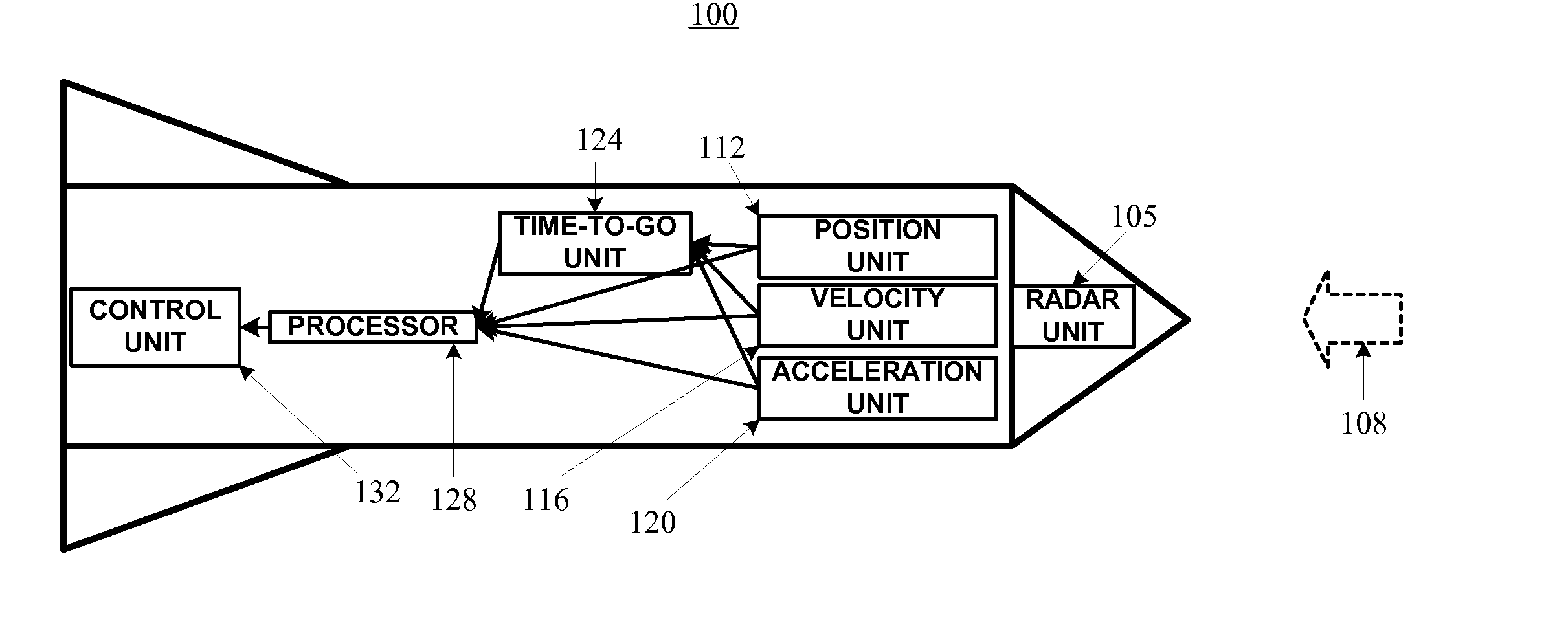
[0011] A first object of the invention is to provide a highly accurate method of estimating the time-to-go, which is not computationally time consuming. A further object of the invention is to provide a method of estimating the time-to-go that remains highly accurate even when the vehicle and / or target velocities change or at large vehicle-to-target angles.
[0012] Yet another object of the invention is to provide a highly accurate method of guiding a vehicle to intercept a target based on the time-to-go. Such a guidance method will not be computationally time consuming. The guidance method will also remain highly accurate in spite of changes in vehicle and / or target velocities and large vehicle-to-target angles.
[0013] These objects are implemented by the present invention, which takes actual, or real time acceleration into account when estimating the anticipated locations of a vehicle and a target / obstacle. By using actual acceleration information, the present invention can generate guidance commands that need only small adjustments, rather than requiring dramatic changes that may be difficult to accomplish. Furthermore, because the present invention more accurately anticipates the locations of the vehicle and the target / obstacle, the present invention provides more time for carrying out the guidance commands. This is especially useful as the small adjustments may be made at lower altitudes where aerodynamic surfaces, such as fins, are more responsive. In the thin air at higher altitudes, aerodynamic surfaces are less responsive, making dramatic changes more difficult.
[0014] Each of these methods can be incorporated in a vehicle and used for guiding or arming the vehicle. The method finds applicability in air vehicles such as missiles and water vehicles such as torpedoes. Vehicles using the invention may be operated either autonomously, or be provided additional and / or updated information during flight to improve accuracy.
[0015] While the invention finds application when a vehicle is intended to intercept a target, it also finds application when a vehicle is not intended to intercept a target. In particular, a further object of the invention is to guide a vehicle during accident avoidance situations. In like manner, another object of the invention is to guide a first vehicle relative to one or more other vehicles and / or obstacles. Such objects of the invention may readily be implemented by notifying a vehicle operator of potential accidents and / or the location of other vehicles and / or obstacles.

Problems solved by technology

In the thin air at higher altitudes, aerodynamic surfaces are less responsive, making dramatic changes more difficult.

Method used


Image

  • Time-to-go missile guidance method and system
  • Time-to-go missile guidance method and system
  • Time-to-go missile guidance method and system

Examples


first embodiment

[0030] Deriving a more accurate time-to-go estimate that accounts for the actual or real time acceleration in the first embodiment begins by modifying the zero-effort-miss distance to include acceleration: z=r+vt+12⁢at2,Eq. ⁢10

where a is the missile-to-target acceleration. As with the velocity v, the missile-to-target acceleration a is a net acceleration and is a function of both the missile and target accelerations. Substituting Eq. 10 into Eq. 2 yields: 12⁢a·at3+32⁢a·vt2+(a·r+v·v)⁢t+v·r=0.Eq. ⁢11

[0031] The following equations (Eqs. 12-14) simplify the remainder of the analysis.

v·r=vr cos α  Eq. 12

a·r=ar cos βEq. 13

a·v=av cos γ  Eq. 14

When a≠0, the following additional equations (Eqs. 15, 16) further simplify the analysis. v_=vaEq. ⁢15r_=raEq. ⁢16

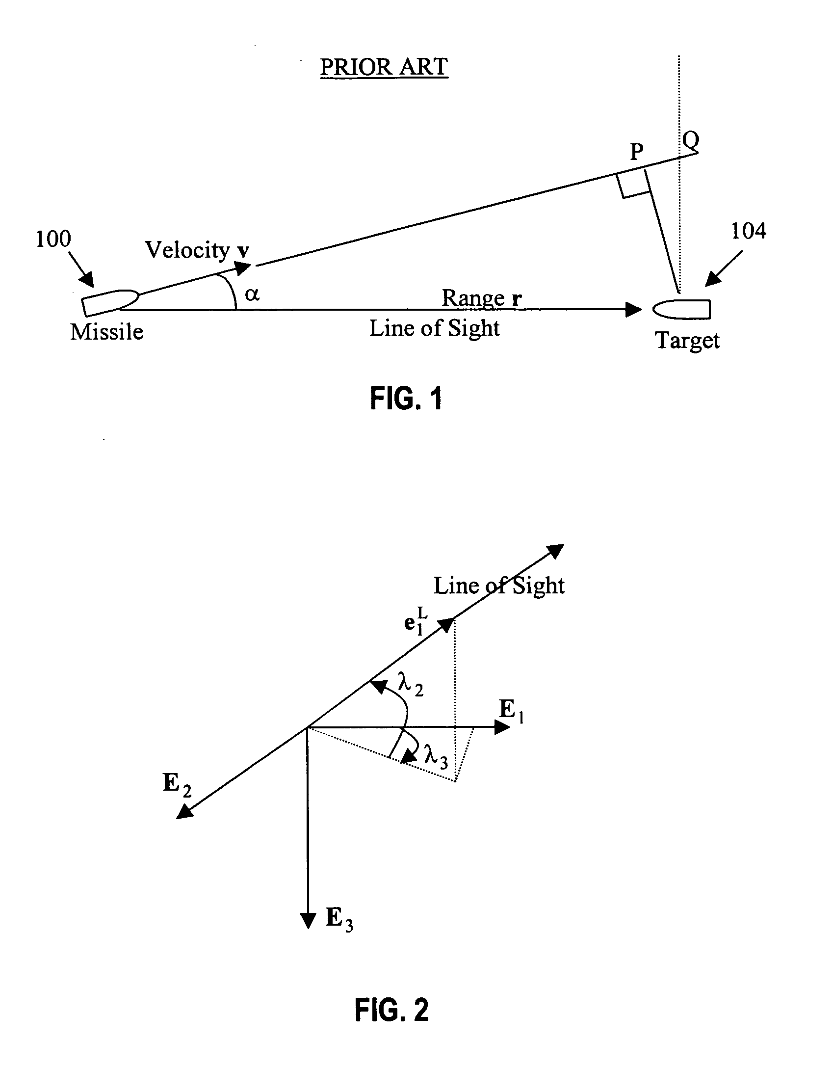
[0032] Substituting Eqs. 12-16 into Eq. 11 yields:

t3+3 v cos γt2+2( r cos β+ v2)t+2 v r cos α=0.  Eq. 17

Defining τ as the time-to-go solution, Eq. 17 becomes:

(t−τ)(t2+bt+c)=0.  Eq. 18

[0033] Eq. 18 has only one real solution, ...

second embodiment

[0041] In the second embodiment, equations based upon three-dimensional relative motion will be developed leading to an analytical solution for true proportional navigation (TPN). The analytical solution to the TPN is then used to derive the time-to-go estimate that accounts for TPN acceleration.

[0042] Let [E1, E2, E3] be the basis vectors of the fixed reference frame. Two additional reference frames will also be employed: the LOS frame and the angular momentum frame. Let [e1L, e2L, e3L] be the basis vectors of the LOS frame, with unit vector e1L aligned with the LOS. Let [e1h, e2h, e3h] be the basis vectors of the angular momentum frame, with unit vector e3h aligned with the angular momentum vector. As will be shown below, the unit vector e1h is aligned with unit vector e1L. Further, the missile-to-target acceleration components expressed in the angular momentum frame can be solved analytically.

[0043] Let λ2 and λ3 be the LOS elevation and azimuth angles, respectively, with respe...

numerical examples

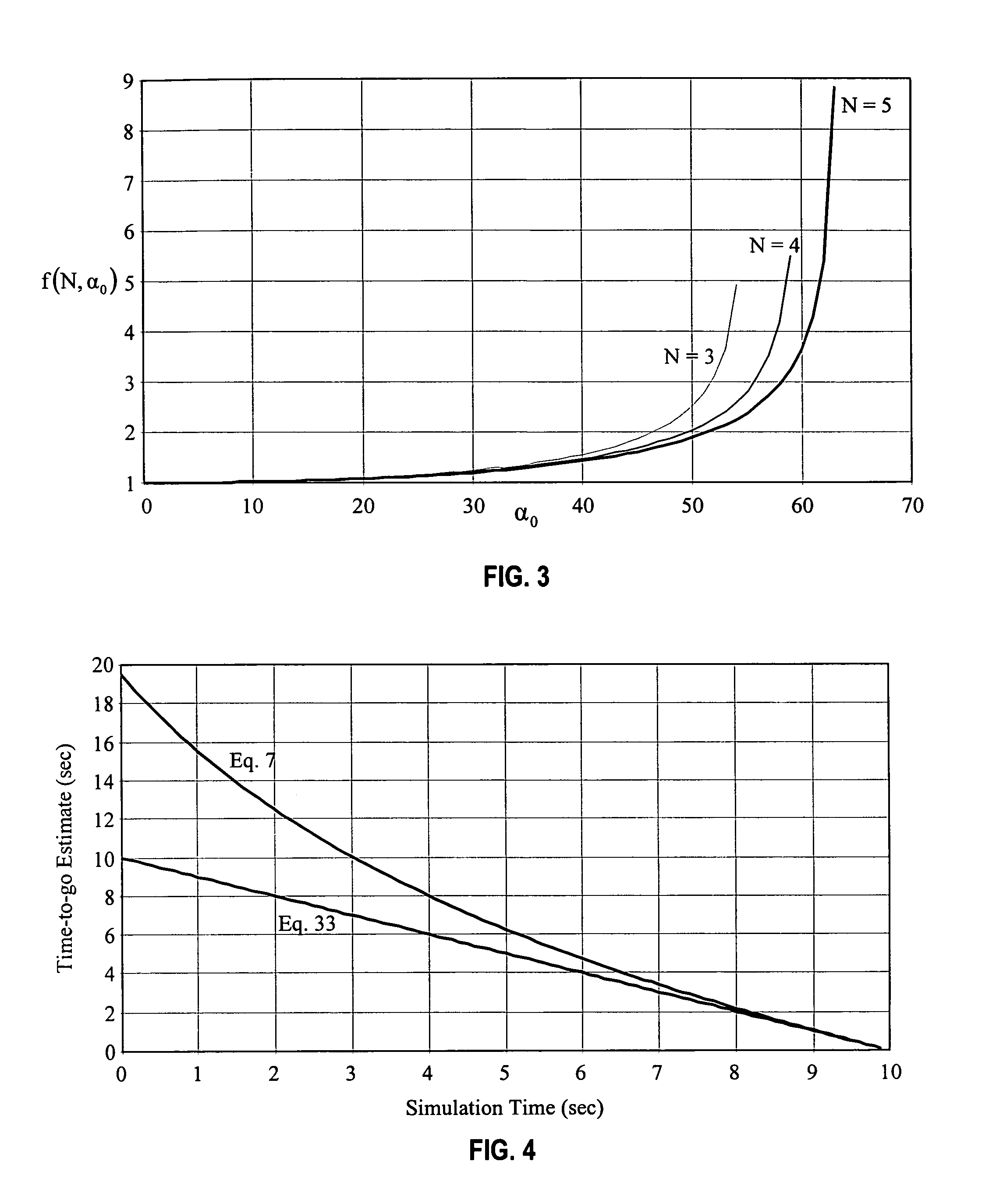
[0081] The results of several numerical examples for time-to-go calculations will now be discussed. In the first example, r=(5000, 5000, 5000), v=(−300, −250, 200), and a=(−40, −50, −60). The results are shown in FIG. 4. It is clear that Eq. 33 yields the exact solution while Eq. 7 returns a large error initially, though the time-to-go error is reduced as the simulation time draws closer to intercept. If a missile, which carries a warhead that must detonate when the missile is close to the target, used Eq. 7 to arm itself, the warhead would uselessly explode far beyond the target as Eq. 7's time-to-go is almost twice the actual time-to-go.

[0082] The second numerical example is a TPN simulation, with a proportional navigation gain N=3. The initial missile and target conditions are:

MissileTargetInitial Position(0, 0, 0)(1000, 1000, 500)Initial Velocity(100, 0, 0)(−10, −5, −5)Initial Acceleration(0, 0, 0)(0, 0, 0)

[0083] The results for several time-to-go approximations are plotted i...


PUM


Abstract

A method and apparatus for guiding a vehicle to intercept a target is described. The method iteratively estimates a time-to-go until target intercept and modifies an acceleration command based upon the revised time-to-go estimate. The time-to-go estimate depends upon the position, the velocity, and the actual or real time acceleration of both the vehicle and the target. By more accurately estimating the time-to-go, the method is especially useful for applications employing a warhead designed to detonate in close proximity to the target. The method may also be used in vehicle accident avoidance and vehicle guidance applications.

Description

FIELD OF THE INVENTION [0001] The present invention relates to a method of and apparatus for guiding a missile. In particular, the present invention provides for a method of guiding a missile based upon the time of flight until the missile intercepts the target, i.e., the time-to-go. BACKGROUND OF THE INVENTION [0002] There is a need to estimate the time it will take a missile to intercept a target or to arrive at the point of closest approach. The time of flight to intercept or to the point of closest approach is known as the time-to-go τ. The time-to-go is very important if the missile carries a warhead that should detonate when the missile is close to the target. Accurate detonation time is critical for a successful kill. Proportional navigation guidance does not explicitly require time-to-go, but the performance of the advanced guidance law depends explicitly on the time-to-go. The time-to-go can also be used to estimate the zero effort miss distance. [0003] One method to estima...

Claims


Application Information

Patent Timeline
IPC IPC(8): F41G7/00
CPCF41G7/2206F42C13/04F41G7/2286F41G7/2246
Inventor LAM, VINCENT C.
Owner LOCKHEED MARTIN CORP
Learn More