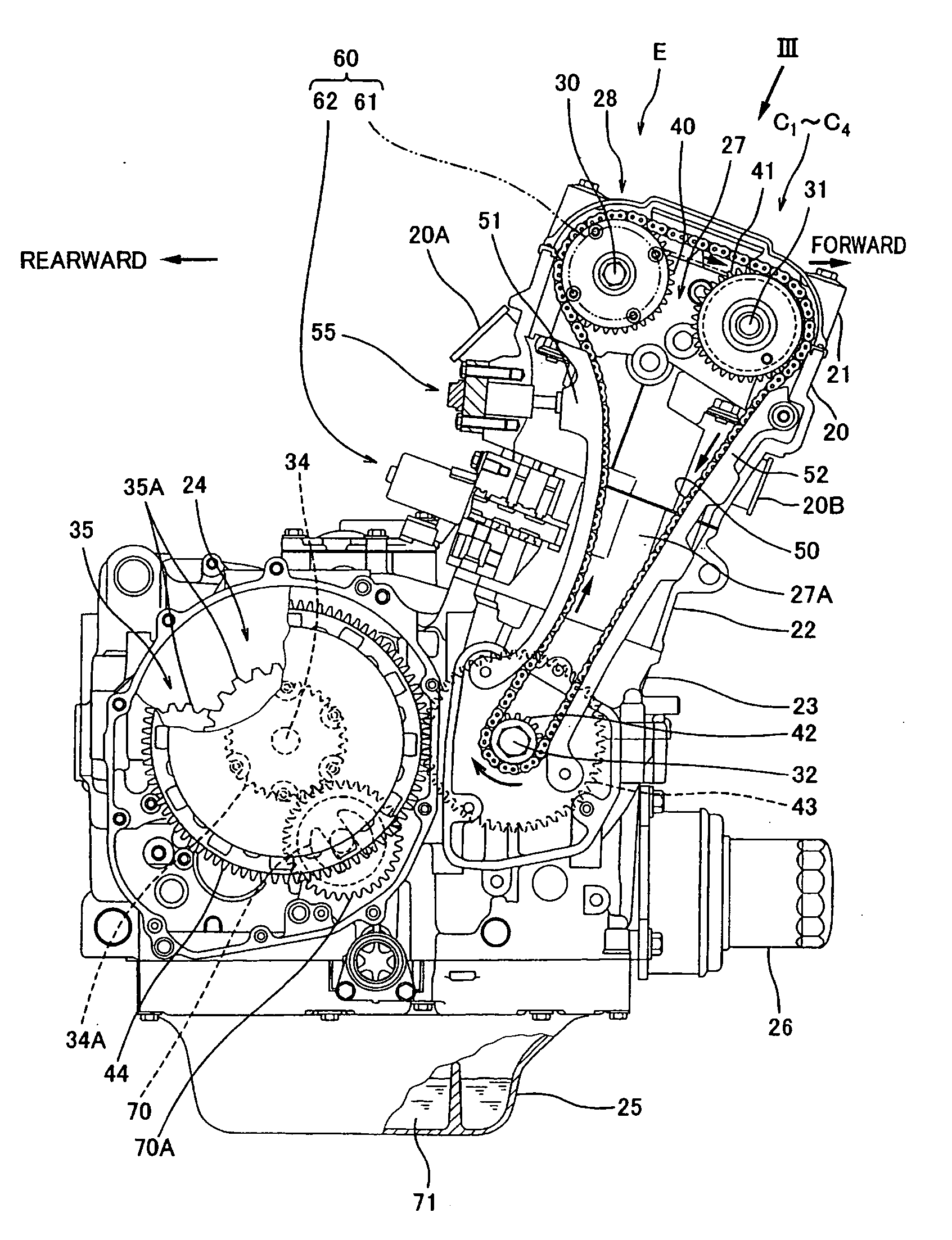
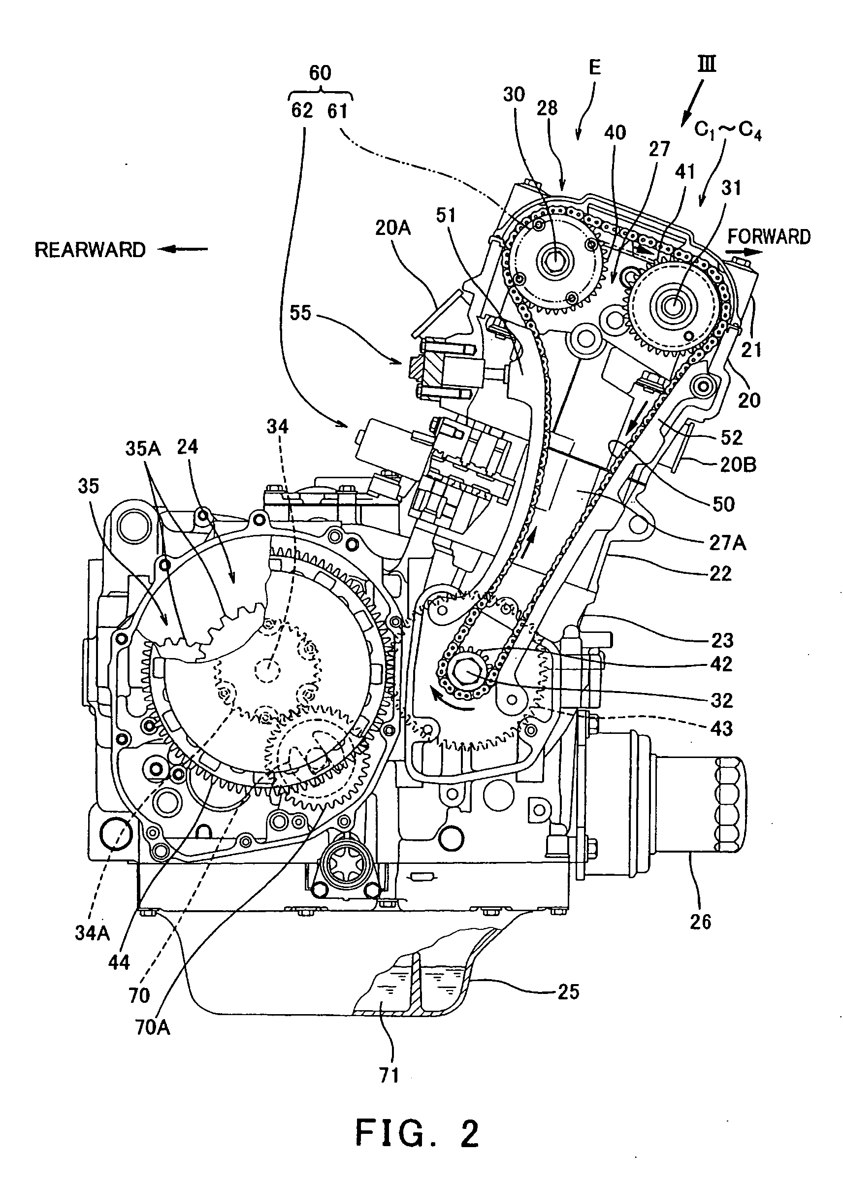
Engine
a technology for engines and oil, applied in the field of engines, can solve problems such as pressure loss of oil, and achieve the effect of reducing the pressure loss of oil
- Summary
- Abstract
- Description
- Claims
- Application Information
AI Technical Summary
Benefits of technology
Problems solved by technology
Method used
Image
Examples
embodiment 1
[0038]FIG. 1 is a right side view of a motorcycle 1 in which an engine E according to an embodiment of the present invention is mounted. The motorcycle 1 is a road sport type motorcycle in which a rider R rides with an upper body leaning forward. Herein, directions are generally referenced from the perspective of the rider R mounting the motorcycle 1 of FIG. 1.
[0039] Turning now to FIG. 1, the motorcycle 1 includes a front wheel 2 and a rear wheel 3. The front wheel 2 is rotatably mounted to a lower region of a front fork 5 extending substantially vertically. The front fork 5 is mounted on a steering shaft (not shown) by an upper bracket (not shown) attached to an upper end thereof, and an under bracket located below the upper bracket. The steering shaft is rotatably supported by a head pipe 6. A bar-type steering handle 4 extending in a rightward and leftward direction is attached to the upper bracket. When the rider R rotates the steering handle 4 clockwise or counterclockwise, t...
embodiment 2
[0085] Subsequently, a second embodiment of the present invention will be described. FIG. 10 is a right side view of the engine E according to the second embodiment. FIG. 11 is a perspective view of the engine E, from which the cylinder head 20 is removed. FIG. 12 is a plan view of the engine E of FIG. 11. FIG. 13 is a cross-sectional view of the engine E, taken substantially along line XIII-XIII of FIG. 12. FIG. 14 is a view schematically showing a construction of oil passages of the engine E.
[0086] Turning now to FIGS. 13 and 14, a primary oil filter 163 is attached to a first oil passage 81 extending between the oil pan 25 that reserves the oil at the lower portion of the engine E and the oil pump 70. A second oil passage 82 is coupled to an output side of the oil pump 70 and to a secondary oil filter 26. In FIG. 13, a passage downstream of a bent portion 82a of the second oil passage 82, which is connected to the secondary oil filter 26, is not shown. A third oil passage 83 is ...
embodiment 3
[0092] Subsequently, a third embodiment of the present invention will be described. FIG. 15 is a view schematically showing a construction of the oil passages of the engine E according to the third embodiment. As shown in FIG. 15, in this embodiment, the oil passage 165 for the hydraulically-powered device that branches in a location of the third oil passage 83 extending between the oil cooler 146 and the secondary oil filter 26 further branches to feed the oil to the hydraulically-powered tensioner 55.
[0093] In the above construction, since the oil pressure without the pressure loss that may be caused by the oil cooler 146 is fed to the hydraulically-powered tensioner 55, the tensioner 55 is able to efficiently apply a forward force to the chain guide 51 (see FIG. 2), thereby applying a suitable tension to the timing chain 50. The other construction is identical to that of the first embodiment, and will not be further described.
PUM
 Abstract
Description
Claims
Application Information
 - R&D
- Intellectual Property
- Life Sciences
- Materials
- Tech Scout
- Unparalleled Data Quality
- Higher Quality Content
- 60% Fewer Hallucinations
Browse by: Latest US Patents, China's latest patents, Technical Efficacy Thesaurus, Application Domain, Technology Topic, Popular Technical Reports.
© 2025 PatSnap. All rights reserved.Legal|Privacy policy|Modern Slavery Act Transparency Statement|Sitemap|About US| Contact US: help@patsnap.com


