Method of connecting signal lines, a printed circuit board assembly and electronic apparatus having the same

a technology of printed circuit board and signal line, which is applied in the direction of coupling device connection, way, instruments, etc., can solve the problems of large size and space, complicated structure of conventional connector structure, and large size and space of conventional printed circuit board assembly, and achieve the effect of simple electrical connection structur

Active Publication Date: 2007-07-05
SAMSUNG ELECTRONICS CO LTD
View PDF2 Cites 2 Cited by
  • Summary
  • Abstract
  • Description
  • Claims
  • Application Information

AI Technical Summary

Benefits of technology

[0010]The present general inventive concept provides a method of connecting signal lines, a printed circuit board assembly, and an electronic apparatus having the same, with a relatively simple electrical connection structure.

Problems solved by technology

However, the conventional connector structure has a complicated structure because of the combination of the connector and the pin coupling member, and requires the process of coupling the connector and the pin coupling member to the boards.
Accordingly, there is a problem that the conventional printed circuit board assembly requires many components and a large size and space thereof.

Method used


Image

  • Method of connecting signal lines, a printed circuit board assembly and electronic apparatus having the same
  • Method of connecting signal lines, a printed circuit board assembly and electronic apparatus having the same
  • Method of connecting signal lines, a printed circuit board assembly and electronic apparatus having the same

Examples


Embodiment Construction

[0048]Reference will now be made in detail to the embodiments of the present general inventive concept, examples of which are illustrated in the accompanying drawings, wherein like reference numerals refer to the like elements throughout. The embodiments are described below in order to explain the present general inventive concept by referring to the figures.

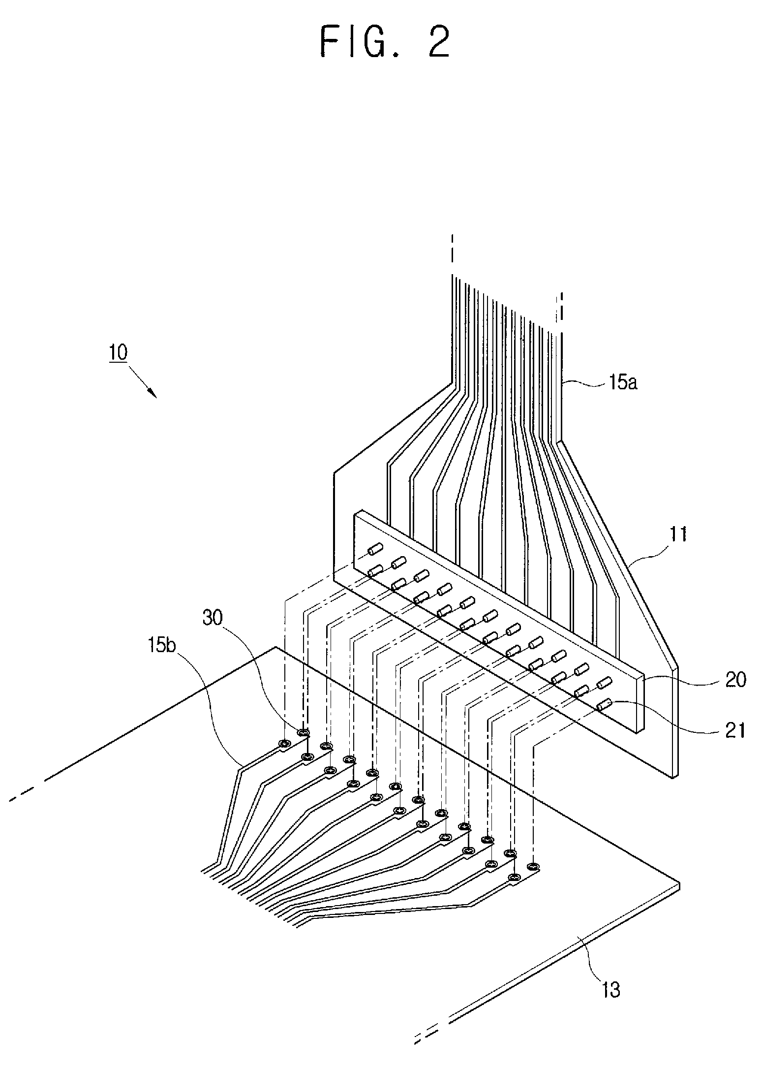
[0049]As illustrated in FIGS. 2 and 3, a printed circuit board assembly 10 according to an embodiment of the present general inventive concept includes a first board 11 and a second board 13 each having signal lines 15a and 15b, a connector 20 provided on the first board 11 and having a plurality of pins 21, and a connector coupling member 30 provided in a surface of the second board 13 and having pin housings 31 which come in contact with the pins 21 by being deformed in a pin coupling direction to electrically connect to the pin 21. Here, the positions of the connector 20 and the connector coupling member 30 may be exchanged a...


PUM


Abstract

A method of connecting signal lines, a printed circuit board assembly and an electronic apparatus having the same. The present general inventive concept provides a printed circuit board assembly in which signal lines are connected between a first board and a second board, including a connector having a plurality of pins provided in one of the first board and the second board, and a connector coupling member having a plurality of pin housings which come in contact with the pins by being deformed in a pin coupling direction to electrically connect to the pins and which are provided in a surface of the other of the first board and the second board.

Description

CROSS-REFERENCE TO RELATED APPLICATIONS[0001]This application claims priority under 35 U.S.C. 119 §(a) from U.S. Patent Application No. 60 / 775,800, filed on Feb. 23, 2006, in the USPTO, and Korean Patent Application No. 2006-0000413, filed on Jan. 3, 2006, in the Korean Intellectual Property Office, the disclosure of which is incorporated herein in their entireties by reference.BACKGROUND OF THE INVENTION[0002]1. Field of the Invention[0003]The present general inventive concept relates to a method of connecting signal lines, a printed circuit board assembly and an electronic apparatus having the same, and more particularly, to a printed circuit board assembly and an electronic apparatus having the same which has an improved electrical connection structure.[0004]2. Description of the Related Art[0005]In general, a printed circuit board assembly includes a printed circuit board (PCB) used as a component of electronic apparatuses from home electronics such as a digital TV and a compute...

Claims


Application Information

Patent Timeline
Patent Type & Authority Applications(United States)
IPC IPC(8): H01R12/00H01R12/71
CPCH01R4/4881H01R12/58H05K3/306H05K3/326H01R12/79H05K2201/091H05K2201/10189H05K2201/1059H05K3/365F21V19/001F21W2111/02F21Y2115/10G08G1/095
Inventor KIM, JAE-YOUNG
Owner SAMSUNG ELECTRONICS CO LTD
Why Eureka
Try Eureka